3.37
Date Code 20060320 Instruction Manual SEL-311C Relay
Distance, Out-of-Step, Overcurrent, Voltage, Synchronism Check, and Frequency Elements
Time-Overcurrent Elements
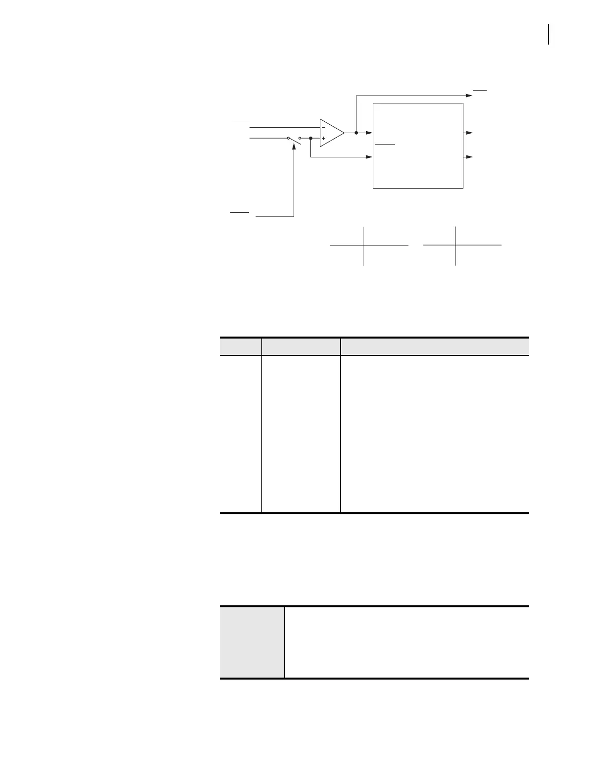
Figure 3.25 Residual Ground Time-Overcurrent Element 51GT
Settings Ranges
See Section 9: Setting the Relay for additional time-overcurrent element
settings information.
Accuracy
51GP
(residual)
I
G
Setting
51GTC
Torque Control Switch
SEL
OGIC
Torque Control
51GT Residual Ground
Time-Overcurrent Element
Curve Timing and Reset Timing
Settings
51GP Pickup
51GC Curve Type
51GTD Time Dial
51GRS Electromechanical
Reset? (Y/N)
Pickup
Curve
Timeout
Reset
51G
51GR
51GT
Torque Control
51GTC State Switch Position
Logical 1 Closed
Logical 0 Open
Logic Point 51GTC Controls the Torque Control Switch
Setting
51GRS = Reset Timing
Y Electromechanical
N 1 Cycle
Relay
Word
Bits
SELOGIC
Setting
Table 3.11 Residual Ground Time-Overcurrent Element Settings
Setting Definition Range
51GP pickup OFF, 0.25–16.00 A secondary
(5 A nominal phase current inputs, IA, IB, IC)
OFF, 0.05–3.20 A secondary
(1 A nominal phase current inputs, IA, IB, IC)
51GC curve type U1–U5 (U.S. curves) see Figure 9.1–Figure 9.10
C1–C5 (I.E.C. curves)
51GTD time dial 0.50–15.00 (U.S. curves) see Figure 9.1–Figure 9.10
0.05–1.00 (I.E.C. curves)
51GRS electromechanical
reset timing
Y = Enable electromechanical reset timing
N = 1-cycle reset delay
51GTC SEL
OGIC control
equation torque
control setting
Relay Word bits referenced in Table 9.5 and Tabl e 9.6
or
set directly to logical 1
a
a
SELOGIC control equation torque control settings (e.g., 51GTC) cannot be set directly to
logical 0.
Pickup
±0.05 A secondary and ±3% of setting
(5 A nominal phase current inputs, IA, IB, IC)
±0.01 A secondary and ±3% of setting
(1 A nominal phase current inputs, IA, IB, IC)
Curve Timing
±1.50 cycles and ± 4% of curve time for currents
between (and including) 2 and 30 multiples of pickup



 To Next Page