7.3
Date Code 20060320 Instruction Manual SEL-311C Relay
Inputs, Outputs, Timers, and Other Control Logic
Optoisolated Inputs
Optoisolated Inputs
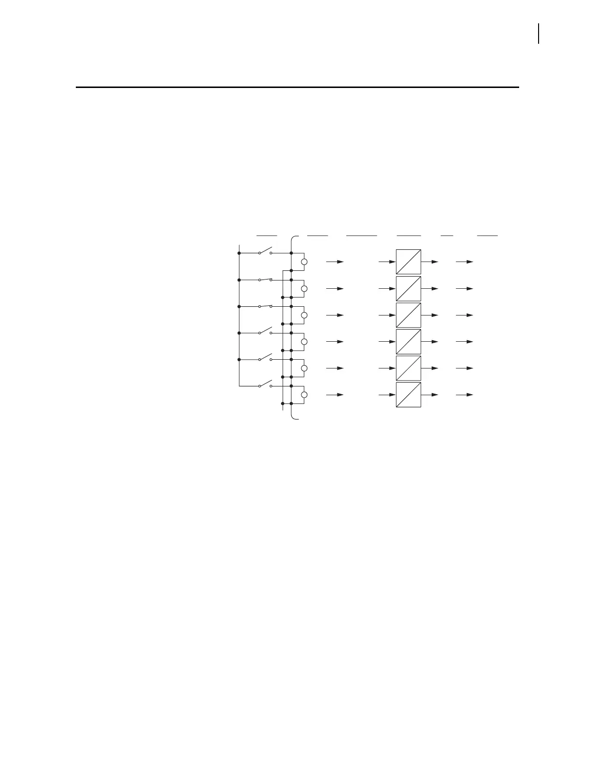
Figure 7.1 and Figure 7.2 show the resultant Relay Word bits that follow
corresponding optoisolated inputs for the different SEL-311C Relay models.
The figures show examples of energized and de-energized optoisolated inputs
and corresponding Relay Word bit states. To assert an input, apply rated
control voltage to the appropriate terminal pair (see Figure 1.2 and Figure 1.3
and Figure 2.2 and Figure 2.8 through Figure 2.11).
Figure 7.1 is used for the following discussion/examples. The optoisolated
inputs in Figure 7.2 operate similarly.
Figure 7.1 Example Operation of Optoisolated Inputs
IN101 Through IN106 (Models 0311C00x and 0311C01x)
Open
IN101 IN101 Logical 0De-energized
Opto-
isolated
Inputs
Example
Switch
States
Built-in
Debounce
Timers
Relay
Word
Bits
Relay
Word Bit
States
Optoisolated
Input States
(+)
(—)
IN101D
IN101D
Closed
IN102 IN102 Logical 1
Energized
IN102D
IN102D
Closed
IN103 IN103 Logical 1
Energized
IN103D
IN103D
Open
IN104 IN104 Logical 0
De-energized
IN104D
IN104D
Open
IN105 IN105 Logical 0
De-energized
IN105D
IN105D
Open
IN106 IN106 Logical 0De-energized
IN106D
IN106D

 Loading...


