13.37
Date Code 20060320 Instruction Manual SEL-311C Relay
Testing and Troubleshooting
Test Procedures
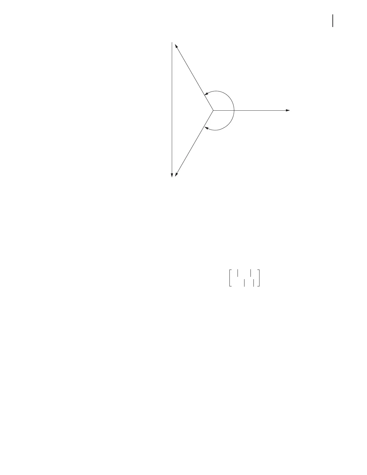
Figure 13.8 Phase Distance Element Test Voltage Signals
Step 13. When the magnitude of V
BC
calculated above lies between 67
and 35 volts, use β = 150° and |V
B
| = |V
C
| = |V
BC
|.
Step 14. When the magnitude of V
BC
calculated above is greater than
67 volts, use |V
B
| = |V
C
| = 67 V.
Step 15. Calculate the angle β through use of Equation 13.38.
Step 16. When the magnitude of V
BC
calculated above is less than
35 volts, use |V
B
| = |V
C
| = 35 V.
Step 17. Calculate the angle β through use of Equation 13.38.
Equation 13.38
Step 18. Select V
A
= 67 ∠0° volts. For the Zone 2 B-C element test,
based upon the example settings, the magnitude of V
BC
equals
46.8 volts. From the equations above, select the following test
voltage magnitudes and angles.
V
A
= 67.0 V ∠0° volts
V
B
= 46.8 ∠–150° volts
V
C
= 46.8 ∠150° volts
The phase distance element maximum reach is measured when
faulted phase-to-phase current lags faulted phase-to-phase
voltage by the distance element maximum torque angle. In the
SEL-311C, the phase distance element maximum torque angle
is defined by the angle of the relay Z1ANG setting.
For the example relay settings, I
BC
should lag V
BC
by 83.97°.
Based upon the test voltages selected above, V
BC
lags V
A
by
90°, so I
BC
should lag V
A
by 173.97°.
As stated above, the phase distance elements are supervised by
the negative-sequence directional element. It is important to
check the negative-sequence quantities applied and verify that
–b
b
Vb
Vc
Vbc
Va
β 180° a sin
V
BC
2V
C
• ()
-------------------------
deg–=

 Loading...


