2.14
SEL-311C Relay Instruction Manual Date Code 20060320
Installation
Making Rear-Panel Connections
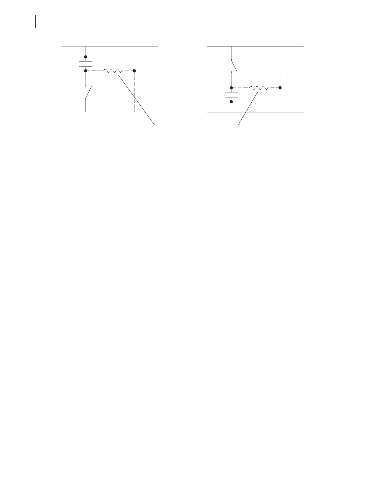
Figure 2.12 Possible Connections for Fast High-Current Interrupting Output Contacts
(Circuit Load Not Shown, Third Terminal Connection Is Optional)
Optoisolated Inputs
The optoisolated inputs in any of the SEL-311C models (e.g., IN102, IN207) are
not polarity dependent. With nominal control voltage applied, each
optoisolated input draws approximately 4 mA of current. Refer to
Specifications on page 1.10 for optoisolated input ratings.
Refer to the serial number sticker on the relay rear panel for the optoisolated
input voltage rating.
Current Transformer
Inputs
Note the polarity dots above terminals Z01, Z03, Z05, and Z07. Refer to
Figure 2.13 and Figure 2.14 for typical CT wiring examples.
Refer to the serial number sticker on the relay rear panel for the nominal
current ratings (5 A or 1 A) for the phase (IA, IB, IC) and polarizing current
inputs.
Potential Transformer
Inputs
Note the signal labels (VA, VB, VC, N, VS, NS) on terminals Z09 through Z14.
Figure 1.2 shows the internal connection for terminals VA, VB, VC, and VN. Note
also that VS/NS is a separate single-phase voltage input.
Wye-Connected
Voltages
Any of the single-phase voltage inputs (i.e., VA-N, VB-N, VC-N, or VS-NS) can be
connected to voltages up to 150 V continuous. Figure 2.13 and Figure 2.14
show examples of wye-connected voltages. System frequency is determined
from the voltages connected to terminals VA-N.
Serial Ports
All ports are independent—you can communicate to any combination
simultaneously.
Serial Port 1 on all the SEL-311C models is an EIA-485 port (4-wire). The
Serial Port 1 plug-in connector accepts wire size AWG 24 to 12. Strip the
wires 0.31 inches (8 mm) and install with a small slotted-tip screwdriver. The
Serial Port 1 connector has extra positions for IRIG-B time-code signal input
(see Table 10.2; also see following discussion on IRIG-B time code input).
All EIA-232 ports accept 9-pin D-subminiature male connectors. Port 2 on all
the SEL-311C models includes the IRIG-B time-code signal input (see
Table 10.1; also see following discussion on IRIG-B time-code input).
The pin definitions for all the ports are given on the relay rear panel and are
detailed in Table 10.1 through Table 10.3 in Section 10: Serial Port
Communications and Commands.
C01
C02
(+)
(–)
C03
C01
C02
C03
(–)
(+)
Circuit for Charge
Current Internal to SEL-311C