7.14
SEL-311C Relay Instruction Manual Date Code 20060320
Inputs, Outputs, Timers, and Other Control Logic
Latch Control Switches
Latch Control Switch
Application Ideas
Latch control switches can be used for such applications as:
➤ Reclosing relay enable/disable
➤ Ground relay enable/disable
Latch control switches can be applied to almost any control scheme. The
following is an example of using a latch control switch to enable/disable the
reclosing relay in the SEL-311C.
Reclosing Relay
Enable/Disable
Setting Example
Use a latch control switch to enable/disable the reclosing relay in the
SEL-311C. In this example, a SCADA contact is connected to optoisolated
input IN104. Each pulse of the SCADA contact changes the state of the
reclosing relay. The SCADA contact is not maintained, just pulsed to enable/
disable the reclosing relay.
Figure 7.13 SCADA Contact Pulses Input IN104 to Enable/Disable
Reclosing Relay
If the reclosing relay is enabled and the SCADA contact is pulsed, the
reclosing relay is then disabled. If the SCADA contact is pulsed again, the
reclosing relay is enabled again. The control operates in a cyclic manner:
pulse to enable ... pulse to disable ... pulse to enable ... pulse to disable ...
This reclosing relay logic is implemented in the following SEL
OGIC control
equation settings and displayed in Figure 7.14.
SET1 = /IN104 * !LT1 [= (rising edge of input IN104) AND NOT(LT1)]
RST1 = /IN104 * LT1 [= (rising edge of input IN104) AND LT1]
79DTL = !LT1 [= NOT(LT1); drive-to-lockout setting]
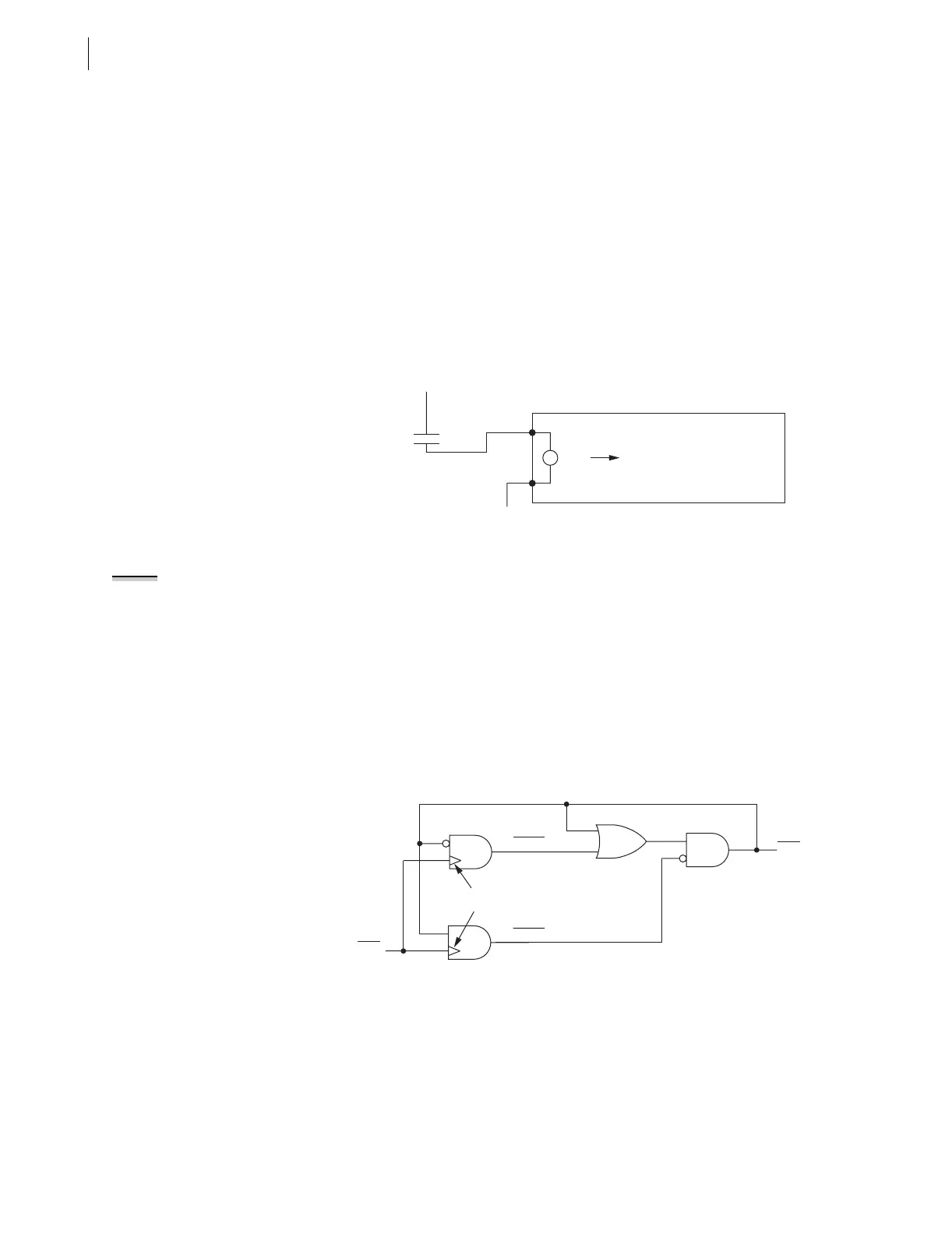
Figure 7.14 Latch Control Switch Controlled by a Single Input to Enable/
Disable Reclosing
Feedback Control
Note in Figure 7.14 that the latch control switch output (latch bit LT1) is
effectively used as feedback for SEL
OGIC control equation settings SET1 and
RST1. The feedback of latch bit LT1 “guides” input IN104 to the correct latch
control switch input.
(+)
SCADA
(—)
Enable/Disable Reclosing Relay
SEL-311C
IN104
NOTE: Refer to Optoisolated Inputs
on page 7.3 and Figure 7.1. Relay Word
bit IN104 shows the state of
optoisolated input IN104 after the
input pickup/dropout debounce timer
IN104D. Thus, when using Relay Word
bit IN104 in Figure 7.13 and associated
SEL
OGIC control equations, keep in
mind any time delay produced by the
input pickup/dropout debounce timer
IN104D.
LT1
IN104
(Set)
(Reset)
Rising Edge
Detect
SET1
RST1
SELOGIC
Setting
SELOGIC
Setting
Relay
Word
Bit
Relay
Word
Bit