2.22
SEL-311C Relay Instruction Manual Date Code 20060320
Installation
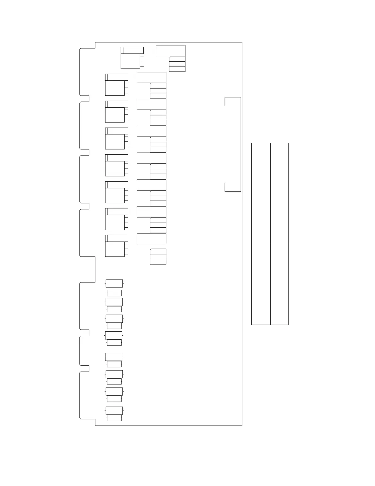
Circuit Board Connections
Figure 2.18 Interface Board 5 Component Layout
Contact opens when asserted
Contact closes when asserted
Operation
Solder Jumper Position
K1 Only, All Others Are Fixed as "a" Contacts
A
B
Output Contacts (8)
Optoisolated Inputs (8)
JMP17
T2
CR1
Q1
T1
CR2
Q2
T4
CR3
Q3
T3
CR4
Q4
T6
CR5
T5
CR6
T8
CR7
T7
CR8
Q8
K2K1 K4K3 K6K5
Q5 Q6
K7
K8
J4
Q7
R57
R58
R61
R62
R59
R60
R63
R64
R49
R50
R55
R56
R51
R52
R53
R54
B
A
-+
-+
-+
-+
-+
-+
-+
-+
(Fast High Current Interrupting)