3.29
Date Code 20060320 Instruction Manual SEL-311C Relay
Distance, Out-of-Step, Overcurrent, Voltage, Synchronism Check, and Frequency Elements
Instantaneous/Definite-Time Overcurrent Elements
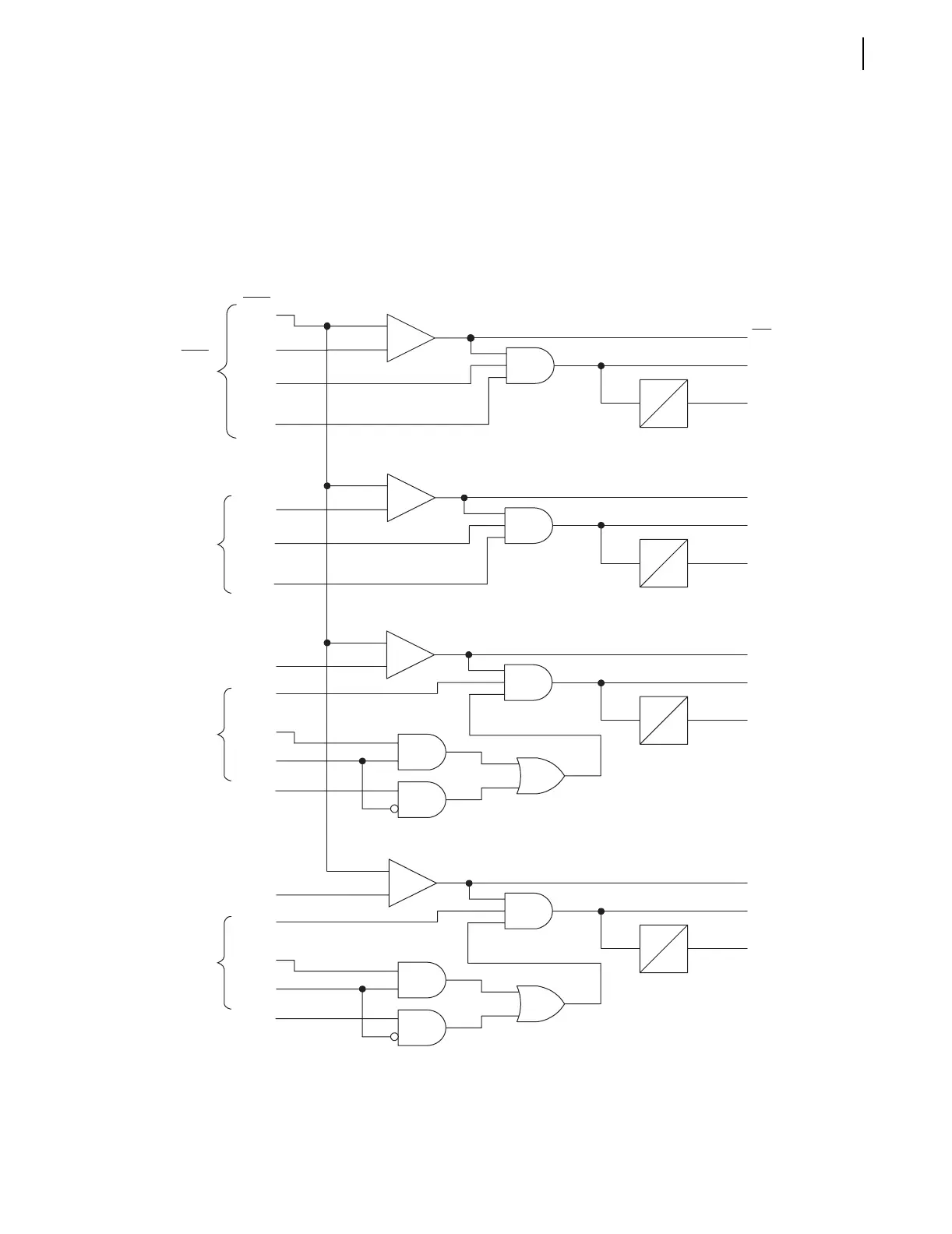
To understand the operation of Figure 3.22, follow the explanation given for
Figure 3.19, substituting residual ground current I
G
(I
G
= 3I
0
= I
A
+ I
B
+ I
C
)
for phase currents and substituting like settings and Relay Word bits.
In Figure 3.22 Levels 1 and 2 67Gn elements have their directional control
fixed forward. Levels 3 and 4 have selectable forward and reverse directional
controls. See Figure 4.12 for more information on directional control.
q From Figure 4.12.
Figure 3.22 Levels 1 Through 4 Residual Ground
Instantaneous/Definite-Time Overcurrent Elements With Directional and Torque Control
_
+
50G2
67G2
67G2T
_
+
50G1P
(Setting)
|3I
0
|
50G1
67G1
67G1T
67G1TC
(SEL
OGIC)
67G2D
0
q 32GF
_
+
50G4
67G4T
67G4
_
+
50G3
67G3
67G3T
67G1D
0
DIR 3 = F
(Setting)
q 32GR
67G3D
0
67G4D
0
Relay
Word
Bits
50G2P
(Setting)
67G2TC
(SEL
OGIC)
50G3P
(Setting)
67G3TC
(SEL
OGIC)
50G4P
(Setting)
67G4TC
(SEL
OGIC)
Relay
Word
Bits
(unless
noted)
Enabled
Levels
q 32GF
q 32GF
DIR 4 = F
(Setting)
q 32GR
q 32GF
Level 1
E50G ≥ 1
(Setting)
Level 2
E50G ≥ 2
(Setting)
Level 3
E50G ≥ 3
(Setting)
Level 4
E50G = 4
(Setting)