2.25
Date Code 20060320 Instruction Manual SEL-311C Relay
Installation
Circuit Board Connections
Note that JMP6 in Figure 2.16 has multiple jumpers A through D. Jumpers A
and B are used (see Table 2.4). Since jumpers C and D are not used, the
positions (ON or OFF) of jumpers C and D are of no consequence.
EIA-232 Serial Port
Voltage Jumpers
The jumpers listed in Table 2.5 connect or disconnect +5 Vdc to Pin 1 on the
corresponding EIA-232 serial ports. The +5 Vdc is rated at 0.5 A maximum
for each port. See Tab le 1 0.1 in Section 10: Serial Port Communications and
Commands for EIA-232 serial port pin functions.
In a standard relay shipment, the jumpers are “OFF” (removed/not in place)
so that the +5 Vdc is not connected to Pin 1 on the corresponding EIA-232
serial ports. Put the jumpers “ON” (in place) so that the +5 Vdc is connected
to Pin 1 on the corresponding EIA-232 serial ports.
Condition of Acceptability for North American Product Safety
Compliance
To meet product safety compliance for end-use applications in North America,
use an external fuse rated 3 A or less in-line with the +5 Vdc source on Pin 1.
SEL fiber-optic transceivers include a fuse that meets this requirement.
Clock Battery
Refer to Figure 2.16 for clock battery B1 location. This lithium battery powers
the relay clock (date and time) if the external power source is lost or removed.
The battery is a 3 V lithium coin cell, Ray-O-Vac
®
No. BR2335 or equivalent.
At room temperature (25°C), the battery will nominally operate for 10 years
with power removed from the relay.
If external power is lost or disconnected, the battery powers the clock. When
the relay is powered from an external source, the battery only experiences a
low self-discharge rate. Thus, battery life can extend well beyond the nominal
10 years because the battery rarely has to discharge after the relay is installed.
The battery cannot be recharged.
If the relay does not maintain the date and time after power loss, replace the
battery. Follow the instructions in Accessing the Relay Circuit Boards on
page 2.19 to remove the relay main board. Remove the battery from beneath
the clip and install a new one. The positive side (+) of the battery faces up.
Reassemble the relay as described in Accessing the Relay Circuit Boards. Set
the relay date and time via serial communications port or front panel (see
Section 10: Serial Port Communications and Commands or Section 11: Front-
Panel Interface (Only on Models With LCD)).
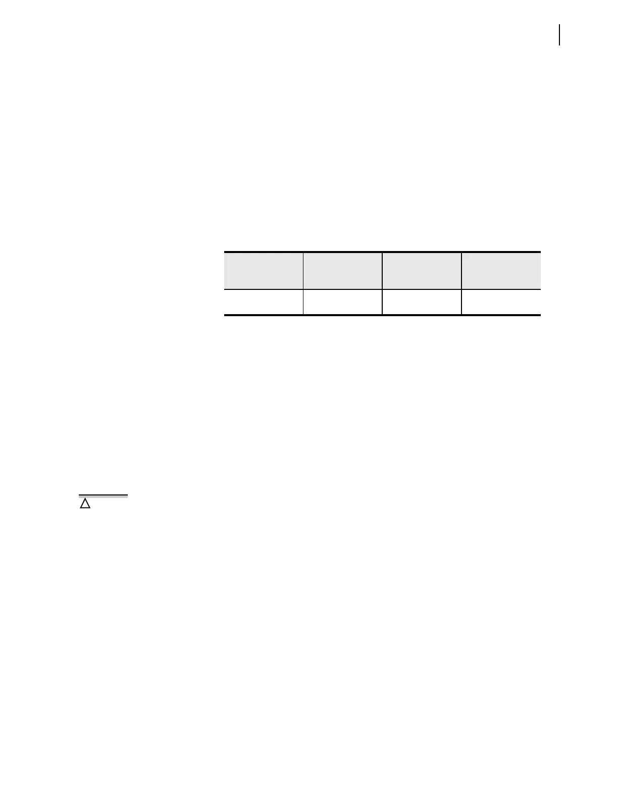
Table 2.5 EIA-232 Serial Port Voltage
Jumper Positions for Standard Relay Shipments
SEL-311C
Model Number
EIA-232
Serial Port 2
(rear panel)
EIA-232
Serial Port 3
(rear panel)
Reference Figure
0311C00x
0311C01x
JMP2 = OFF JMP1 = OFF Figure 2.16
There is danger of explosion if the
battery is incorrectly replaced.
Replace only with Ray-O-Vac
®
no.
BR2335 or equivalent recommended
by manufacturer. Dispose of used
batteries according to the
manufacturer’s instructions.
!
CAUTION