Date Code 20060320 Instruction Manual SEL-311C Relay
Section 4
Loss-of-Potential, CCVT Transient
Detection, Load-Encroachment, and
Directional Element Logic
Loss-of-Potential Logic
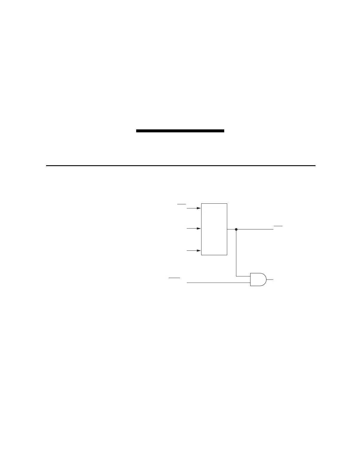
The loss-of-potential (LOP) logic operates as shown in Figure 4.1.
q From Figure 5.3; w to Figure 4.9, Figure 4.10, Figure 4.11, Figure 4.14, and
Figure 4.15.
Figure 4.1 Loss-of-Potential Logic
Inputs into the LOP logic are:
The circuit breaker has to be closed (Relay Word bit 3PO = logical 0) for the
LOP logic to operate.
Loss-of-potential is declared (Relay Word bit LOP = logical 1) when a
10 percent drop in V
1
is detected, with no corresponding change in I
1
or I
0
. If
the LOP condition persists for 60 cycles, it latches in. LOP resets (Relay Word
bit LOP = logical 0) when all three of the phase voltages return above 40 V
secondary, V
0
is less than 5 V secondary, and V
2
is less than 15 percent of V
1
.
3PO three-pole open condition (indicates circuit breaker open
condition see Figure 5.3)
V
1
positive-sequence voltage (V secondary)
I
1
positive-sequence current (A secondary)
V
0
zero-sequence voltage (V secondary)
I
0
zero-sequence current (A secondary)
V
2
negative-sequence voltage (V secondary)
LOP
ELOP = Y or Y1
q 3PO
Loss-of-
Potential
Logic
ILOP w
V
1
, I
1
, I
0
Relay
Word
Bit
Relay
Word
Bits
Setting
V
0
, V
2