13.13
Date Code 20060320 Instruction Manual SEL-311C Relay
Testing and Troubleshooting
Relay Testing
k. Press {SELECT}.
l. Use the left, right, up and down arrow keys to change
the setting to:
LL = 99.00
m. Press {SELECT}.
n. Press {EXIT}.
o. Press {SELECT}
(YES) to save the new settings.
Purpose: Test the fault locator.
Method:
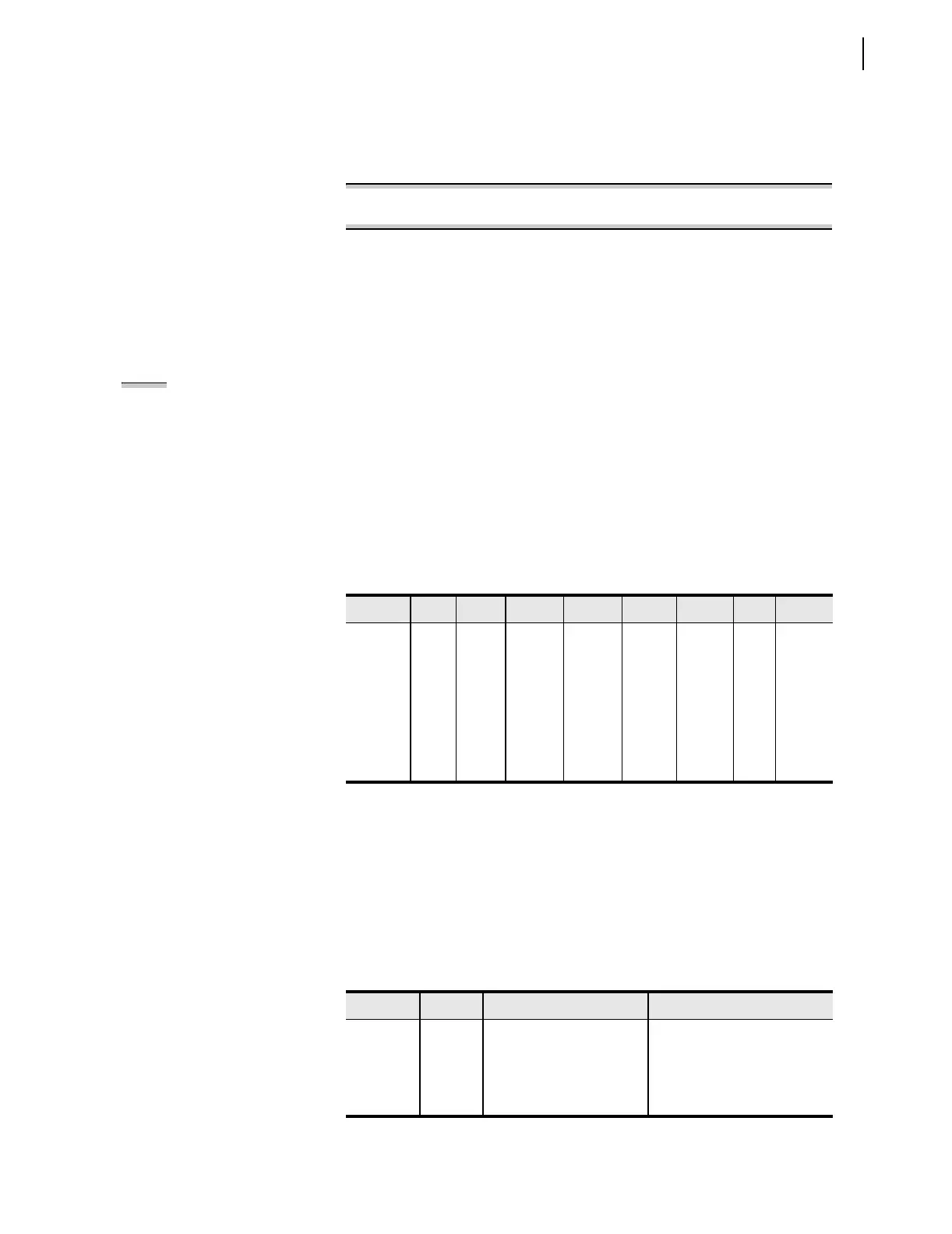
Step 1. Test the fault locator by using the voltages and currents in
Table 13.2.
These voltages and currents were obtained for various locations
and fault types, assuming a radial line with a source impedance
of 0.2 times the total 100-mile line impedance.
Step 2. Run ground fault tests by using the test source connections
shown in Figure 13.2, Figure 13.3, or Figure 13.5. Run phase-
to-phase fault tests by using the test source connections shown
in Figure 13.3 or Figure 13.6.
Faults at 75 miles are within Zone 1, since the Zone 1 reach setting is
80 percent of the 100-mile line positive-sequence impedance (see Z1P,
Z1MG, and XG1 in the settings). Faults at 85 miles are beyond Zone 1, but
within Zone 2.
Faults listed in Table 13.2 cause certain combinations of output contacts to
close and front-panel LEDs to illuminate. You can use the front-panel LCD
functions to examine the short form fault data following each test. Table 13.3
shows the expected results.
Table 13.2 Fault Locator Test Values
Location Type VA VB VC IA IB IC Units
75 miles AG 52.89
0.00
69.97
–124.30
70.34
124.10
5.24
–82.40
0.00
0.00
0.00
0.00
V or A
Degrees
BC 67.00
0.00
56.75
–126.20
56.75
126.20
0.00
0.00
7.83
–174.00
7.83
6.00
V or A
Degrees
85 miles AG 54.24
0.00
69.67
–123.90
70.00
123.70
4.74
–82.40
0.00
0.00
0.00
0.00
V or A
Degrees
BC 67.00
0.00
57.69
–125.50
57.69
125.50
0.00
0.00
7.08
–174.00
7.08
6.00
V or A
Degrees
Table 13.3 Output Contact and Target LED Results
Location Type Output Relays Targ et L E D s
75 miles AG OUT1, OUT2, OUT4 INST, Zone 1, A, G
75 miles BC OUT1, OUT2, OUT4 INST, Zone 1, B, C
85 miles AG OUT1, OUT2, OUT4 TIME, Zone 2, A, G
85 miles BC OUT1, OUT2, OUT4 TIME, Zone 2, B, C
NOTE: To simplify this step, apply dc
voltage to the IN101 input. The relay
recognizes the asserted input when
applied dc voltage is approximately
equal to the Logic Input voltage rating
shown on the relay identification
sticker. Input IN101 is programmed to
monitor the breaker auxiliary contact,
52A. Energize the IN101 input for the
duration of this step to block the
Switch-Onto-Fault logic from
operating. If dc voltage source is not
available, set ESOTF = N in the relay
settings.

 Loading...


