7.16
SEL-311C Relay Instruction Manual Date Code 20060320
Inputs, Outputs, Timers, and Other Control Logic
Latch Control Switches
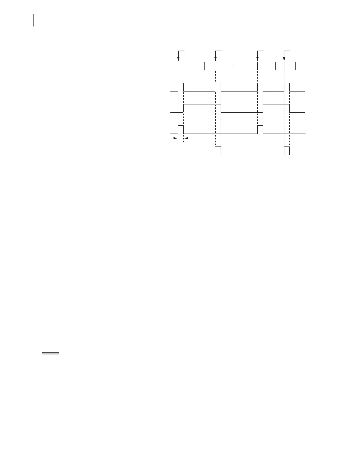
Figure 7.15 Latch Control Switch Operation Time Line
Use a Remote Bit Instead to Enable/Disable the Reclosing Relay
Use a remote bit to enable/disable the reclosing relay, instead of an
optoisolated input. For example, substitute remote bit RB1 for optoisolated
input IN104 in the settings accompanying Figure 7.14:
SET1 = /RB1 * !LT1 [=(rising edge of remote bit RB1) AND NOT(LT1)]
RST1 = /RB1 * LT1 [= (rising edge of remote bit RB1) AND LT1]
79DTL = !LT1 [= NOT(LT1); drive-to-lockout setting]
Pulse remote bit RB1 to enable reclosing, pulse remote bit RB1 to disable
reclosing, etc.—much like the operation of optoisolated input IN104 in the
previous example. Remote bits (Relay Word bits RB1–RB16) are operated
through the serial port. See Figure 7.10 and Section 10: Serial Port
Communications and Commands for more information on remote bits.
These are just a few control logic examples—many variations are possible.
Latch Control Switch
States Retained
Power Loss
The states of the latch bits (LT1–LT16) are retained if power to the relay is lost
and then restored. If a latch bit is asserted (e.g., LT2 = logical 1) when power
is lost, it comes back asserted (LT2 = logical 1) when power is restored. If a
latch bit is deasserted (e.g., LT3 = logical 0) when power is lost, it comes back
deasserted (LT3 = logical 0) when power is restored. This feature makes the
latch bit feature behave the same as traditional latching relays. In a traditional
installation, if power is lost to the panel, the latching relay output contact
position remains unchanged.
Settings Change or Active Setting Group Change
If individual settings are changed (for the active setting group or one of the
other setting groups) or the active setting group is changed, the states of the
latch bits (Relay Word bits LT1–LT16) are retained, much like in the Power
Loss on page 7.16 explanation.
RST1 = /IN104 * LT1
/IN104
IN104
SET1 = /IN104 * !LT1
Rising
Edge
One
Processing
Interval
Pulse 1 Pulse 2 Pulse 3 Pulse 4
Rising
Edge
Rising
Edge
Rising
Edge
LT1
NOTE: Although the relay retains the
state of a latched bit when power is
cycled, the relay cannot hold output
contact closure when power is
removed from the relay (output
contacts go to their de-energized
states).



 To Next Page