7.30
SEL-311C Relay Instruction Manual Date Code 20060320
Inputs, Outputs, Timers, and Other Control Logic
SEL
OGIC Control Equation Variables/Timers
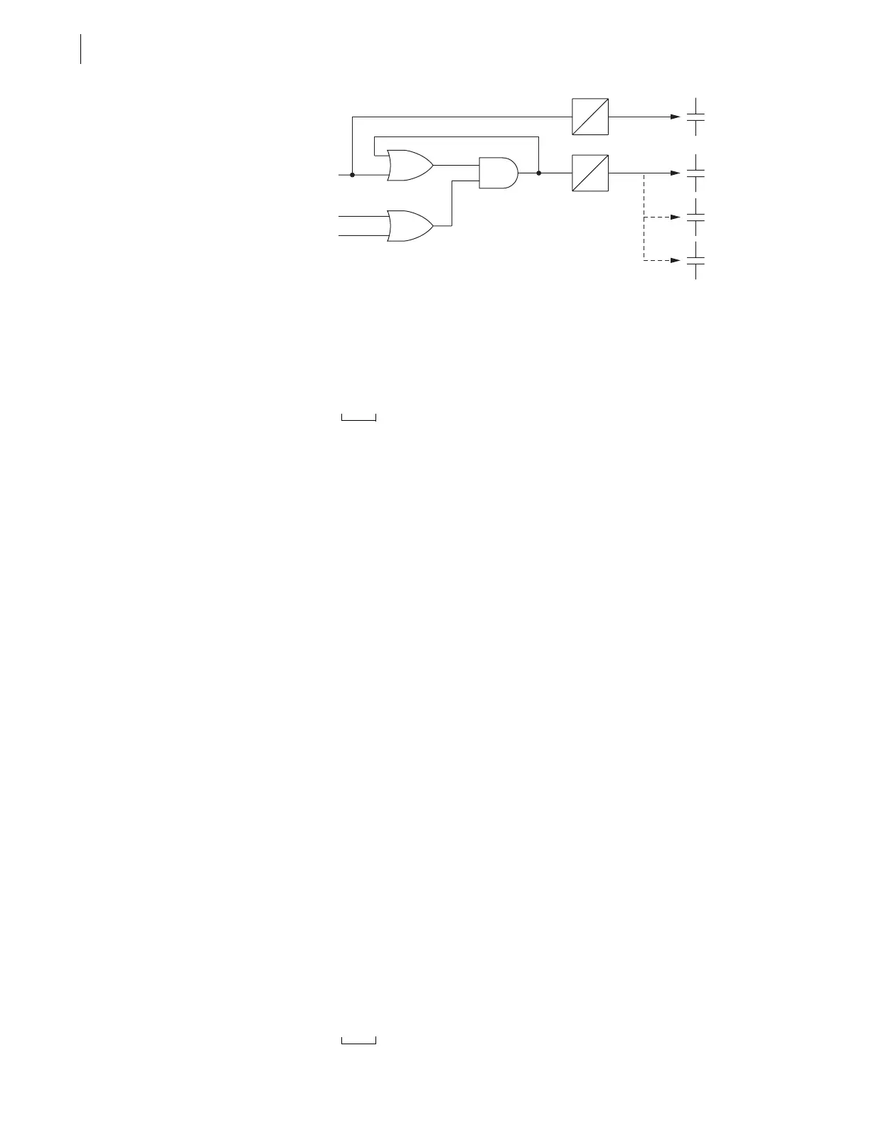
Figure 7.26 Dedicated Breaker Failure Scheme Created With SELOGIC Control
Equation Variables/Timers
Note that the above SELOGIC control equation setting SV7 creates a seal-in
logic circuit (as shown in Figure 7.26) by virtue of SEL
OGIC control equation
setting SV7 being set equal to Relay Word bit SV7 (SEL
OGIC control equation
variable SV7):
SV7 = (SV7 + IN101) * (50P1 + 50G1)
Optoisolated input IN101 functions as a breaker failure initiate input. Phase
instantaneous overcurrent element 50P1 and residual ground instantaneous
overcurrent element 50G1 function as fault detectors.
Timer pickup setting SV6PU provides retrip delay, if desired (can be set to
zero). Timer dropout setting SV6DO holds the retrip output (output contact
OUT101) closed for extra time if needed after the breaker failure initiate signal
(IN101) goes away.
Timer pickup setting SV7PU provides breaker failure timing. Timer dropout
setting SV7DO holds the breaker failure trip output (output contact OUT102)
closed for extra time if needed after the breaker failure logic unlatches (fault
detectors 50P1 and 50G1 dropout).
Note that Figure 7.26 suggests the option of having output contacts OUT103 and
OUT104 operate as additional breaker failure trip outputs. This is done by
making the following SEL
OGIC control equation settings:
OUT103 = SV7T (breaker failure trip)
OUT104 = SV7T (breaker failure trip)
Additional
Settings Example 2
The seal-in logic circuit in the dedicated breaker failure scheme in Figure 7.26
can be removed by changing the SEL
OGIC control equation setting SV7 to:
SV7 = IN101 * (50P1 + 50G1)
If the seal-in logic circuit is removed, optoisolated input IN101 (breaker failure
initiate) has to be continually asserted for a breaker failure time-out.
Timers Reset When
Power Is Lost,
Settings Are
Changed, or Active
Setting Group Is
Changed
If power is lost to the relay, settings are changed (for the active setting group),
or the active setting group is changed, the SEL
OGIC control equation
variables/timers are reset. Relay Word bits SVn and SVnT (n = 1–16) are reset
to logical 0 and corresponding timer settings SVnPU and SVnDO load up
again after power restoration, settings change, or active setting group switch.
Preceding Figure 7.26 shows an effective seal-in logic circuit, created by use
of Relay Word bit SV7 (SEL
OGIC control equation variable SV7) in SELOGIC
control equation SV7:
SV7 = (SV7 + IN101) * (50P1 + 50G1)
IN101
50P1
50N1
SV7 SV7T
SV6 SV6T
OUT101
(Retrip)
OUT102
(Breaker
Failure
Trip)
OUT103
OUT104
SV7PU
SV6PU
SV6D0
SV7D0