14.21
Date Code 20060320 Instruction Manual SEL-311C Relay
Application Settings for SEL-221 Series Relays
SEL-221H to SEL-311C Settings Conversion Guide
Convert SEL-221H
Output Mask Logic
Settings to SELOGIC
Control Equations
See Programmable Output Contact Mask Settings in Section 5: Applications
in the SEL-221H Instruction Manual for a description of output masks. In the
SEL-311C, output masks are replaced by SEL
OGIC control equations as
shown in Table 14.10.
51GTC
(= 1
(= 32GF
= 51NTC (51GTC is
an SEL-311C SEL
OGIC setting)
= N)
= Y)
Time-Overcurrent Elements on
page 3.33
DIR3 = Zone 3 Directional Control Settings on
page 4.21
Section 5—Zone 3
Direction Setting
ORDER Q
V
I
= 32QE
= 32VE
= 32IE
Directional Control for Ground
Distance and Residual Ground
Overcurrent Elements on
page 4.9
Section 2—Directional Elements
52AEND = 52BT (Pickup) Switch-Onto-Fault Trip Logic
on page 5.7
Section 5—High Set Phase Over-
current Setting (50H)
SOTFD = 52BT (Dropout)
Z3RBD = Z3RBT Permissive Overreaching Trans-
fer Trip Logic on page 5.13
Section 5—Zone 3 Reverse Block
Timer Setting (Z3RBT)
EBLKD = None
ETDPU = ETDPU
EDURD = EDUR
EWFC = WFCE
27PPW = 27PP
59NW = 59N
TDURD = TDUR Unlatch Trip on page 5.4 Section 5—Trip Duration Timer
(TDUR)
SV1PU = A1TP
SV1DO = A1TD
SV2PU = 50MFD
a
SEL-311C phase-to-phase fault detector settings 50PP1, 50PP2, and 50PP3 are set to 0.1 •I
NOM
and are hidden. This corresponds to
SEL-221H setting 50L.
b
Curve U1 in the SEL-311C is slightly different from curve 1 in the SEL-221H. Time dial adjustments may be necessary.
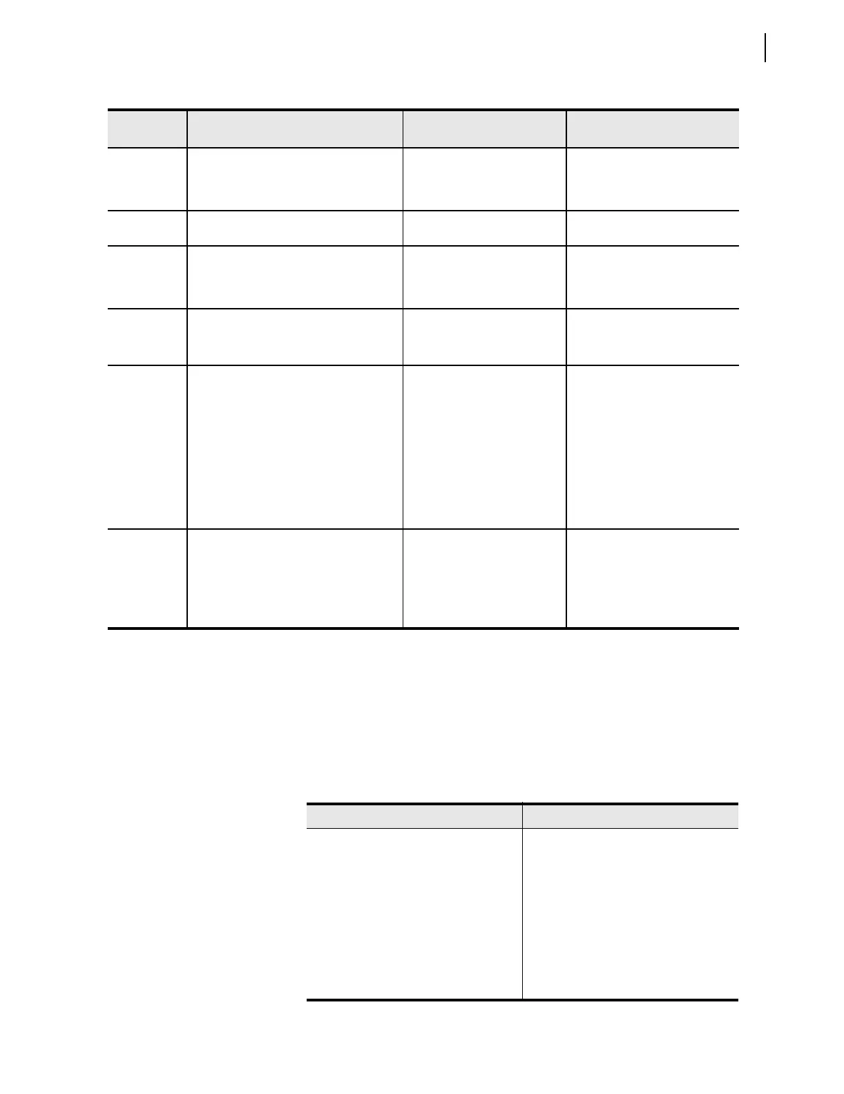
Table 14.9 SEL-311C Settings Calculated From SEL-221H Settings (Sheet 3 of 3)
SEL-311C
Setting
a
Calculated From SEL-221H Settings
SEL-311C Instruction
Manual Section
SEL-221H Instruction
Manual Section
Ta ble 1 4.10 SE L- 31 1C SE LOGIC Control Equation Equivalent to Each
SEL-221H Mask Logic Setting
SEL-221H Settings Mask SEL-311C SELOGIC Control Equations
MTU TR
MPT TRCOMM
MTB SV4
MTO TRSOTF
MA1 OUT104
MA2 OUT105
MA3 OUT106
MA4 OUT107

 Loading...


