7.34
SEL-311C Relay Instruction Manual Date Code 20060320
Inputs, Outputs, Timers, and Other Control Logic
Output Contacts
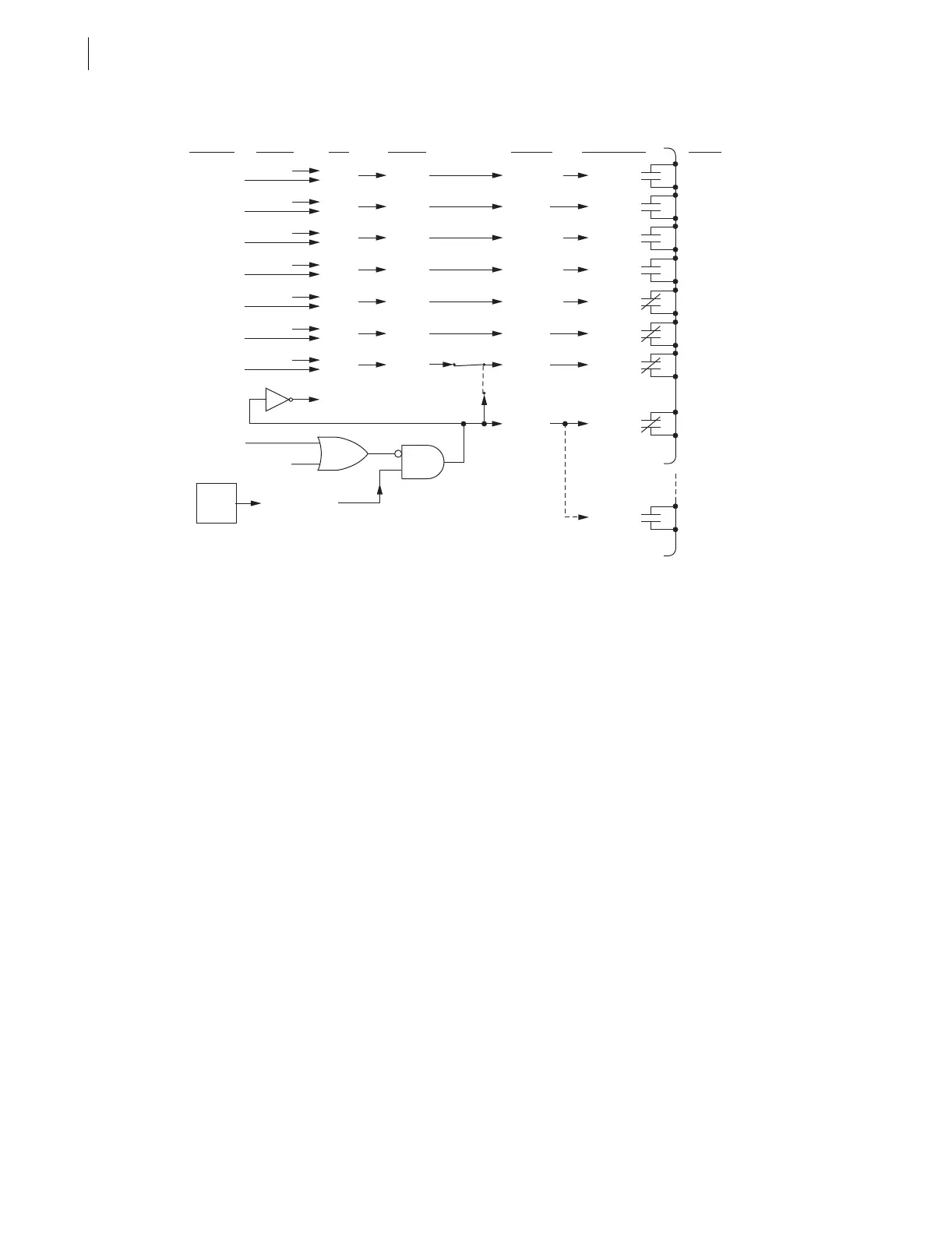
q The PULSE command is also available via the front-panel {CNTRL} pushbutton, “output contact testing” option. Execution
of the PULSE command results in a logical 1 input into the above logic (one-second default pulse width).
w Output contacts OUT101–ALARM are configurable as a or b type output contacts. See Table 2.2 and accompanying text for
more information on selecting output contact type.
e Main board jumper JMP23 allows output contact OUT107 to operate as: regular output contact OUT107 (JMP23 in position
2–3), an extra ALARM output contact (JMP23 in position 1–2). See Table 2. 3 for more information on jumper JMP23.
Figure 7.27 Logic Flow for Example Output Contact Operation (Models 0311C00x and 0311C01x)
OpenOUT101 (a)De-energizedLogical 0OUT101
OUT101
PULSE OUT101
Output
Contact
Coil States
SEL
OGIC
Control
Equations
Settings
Relay
Word
Bits
Example
Relay
Word Bit
States
Serial Port
Commands
(see
q
)
Output Contacts
(and example
contact types)
(see
w
)
Output
Contact
Terminal
States
ClosedOUT102 (a)EnergizedLogical 1OUT102
OUT102
PULSE OUT102
OpenOUT103 (a)De-energizedLogical 0OUT103
OUT103
PULSE OUT103
OpenOUT104 (a)De-energizedLogical 0OUT104
OUT104
PULSE OUT104
ClosedOUT105 (b)De-energizedLogical 0OUT105
OUT105
PULSE OUT105
OpenOUT106 (b)EnergizedLogical 1OUT106
OUT106
PULSE OUT106
OpenOUT107 (b)Energized
Energized
or
De-energized
Logical 1 (relay OK)
or
Logical 0 (relay failed)
Logical 1
(Position 2—3)
(Position 1—2)
JMP23
(see
e
)
Alarm
Logic/
Circuitry
OUT107
OUT107
PULSE OUT107
PULSE ALARM
Relay Enters Access Level 2
Open (relay OK)
or
Closed (relay failed,
de-energized,
etc.)
ALARM (b)
ALARM
Closed (relay OK)
or
Open (relay failed,
de-energized,
etc.)
ALARM (a)

 Loading...


