3.12
SEL-311C Relay Instruction Manual Date Code 20060320
Distance, Out-of-Step, Overcurrent, Voltage, Synchronism Check, and Frequency Elements
Distance Elements
Note 1: mAG = A-Phase to Ground Distance Calculation, Z2MG = Zone 2 Distance Setting.
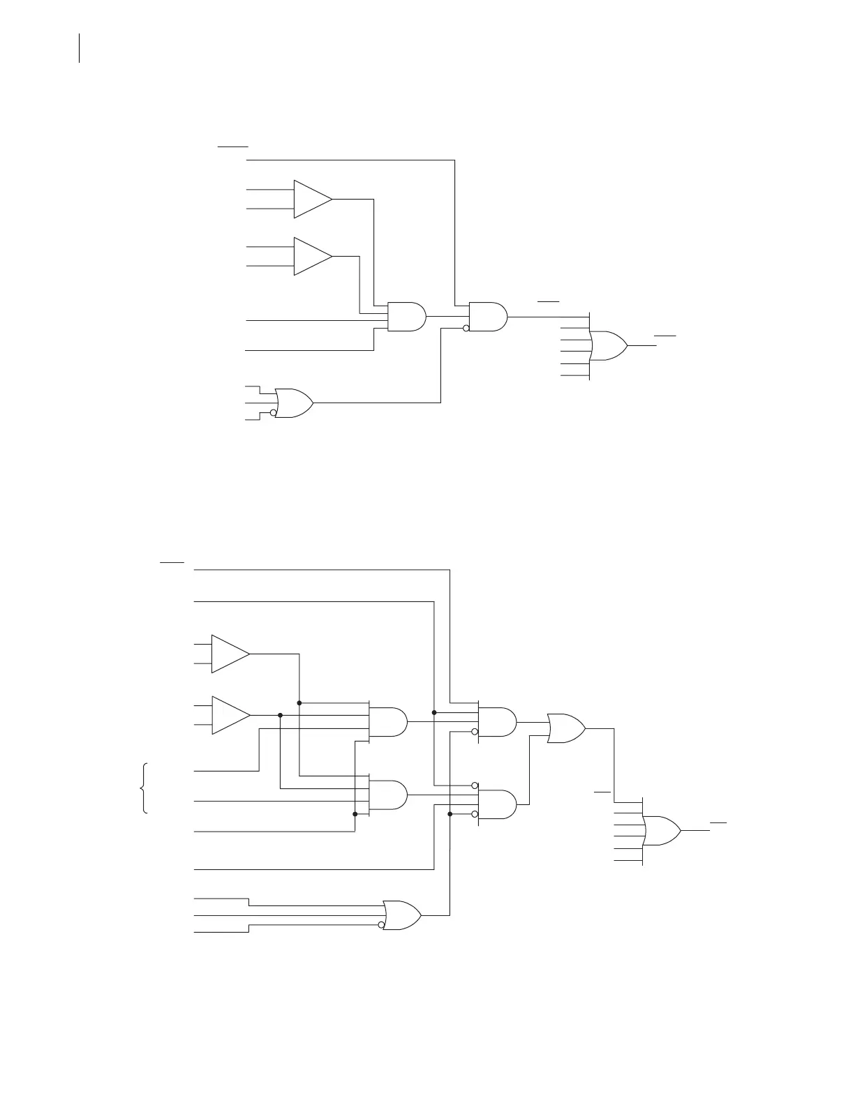
q From Figure 4.12; w from Figure 5.3; e from Figure 4.1.
Figure 3.8 Zone 2 Mho Ground Distance Logic
Note 1: mAG = A-Phase to Ground Distance Calculation, ZnMG = Zone n Distance Setting, n = 3 for Zone 3, n = 4 for
Zone 4.
q From Figure 4.12; w from Figure 5.3; e from Figure 4.1.
Figure 3.9 Zones 3 and 4 Mho Ground Distance Logic
|IA|
50L2
(Advanced Setting)
q 32GF
_
+
_
+
|IG|
50GZ2
(Advanced Setting)
See Note 1 mAG < Z2MG
FSA
w 3PO
e ILOP
VPOLV
Zone 2 A-Phase Mho Ground Distance Logic.
B and C Phase Logic Is Similar.
Relay
Word
Bits
(unless
noted)
MAG2
MBG2
MCG2
XAG2
XBG2
XCG2
Z2G
Relay
Word
Bits
Relay
Word
Bit
DIRn = F
(Setting)
q 32GF
|IA|
50Ln
(Advanced Setting)
mAG < ZnMG
FSA
w 3PO
e ILOP
VPOLV
_
+
Zone 3 and 4 A-Phase Mho Ground Distance Logic.
B- and C-Phase Logic Is Similar.
q 32GR
_
+
|IG|
50GZn
(Advanced Setting)
MAGn
MBGn
MCGn
XAGn
XBGn
XCGn
ZnG
mAG > –ZnMG
See
Note 1
Relay
Word
Bits
Relay
Word
Bit
Relay
Word
Bits
(unless
noted)