3.11
Date Code 20060320 Instruction Manual SEL-311C Relay
Distance, Out-of-Step, Overcurrent, Voltage, Synchronism Check, and Frequency Elements
Distance Elements
Note 1: mAG = A-Phase to Ground Distance Calculation, Z1MG = Zone 1 Distance Setting, X1 = Zone 1 Extension t.
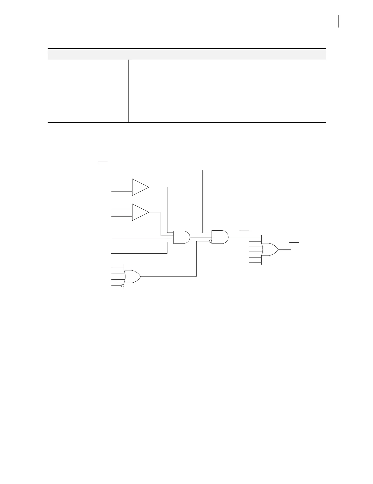
q From Figure 4.12; w from Figure 4.2; e from Figure 5.3; r from Figure 4.1; t from Figure 3.15.
Figure 3.7 Zone 1 Mho Ground Distance Logic
Settings range for
quadrilateral ground
polarizing quantity (hidden and set
to I2 when EADVS = N)
XGPOL =
I2 (negative-sequence current) or I0 (zero-sequence current) (advanced setting)
Settings range for nonhomogeneous
correction angle (hidden
and set to –3 when EADVS = N)
TANG = –40 to +40 degrees (advanced setting)
a
If EADVS = N, levels 2–4 fault detectors are set at their minimum values and are hidden.
Table 3.3 Ground Distance Elements Settings (Sheet 2 of 2)
Impedance Reach (Zones 1–4)
|IA|
50L1
(Setting)
q 32GF
_
+
_
+
|IG|
50GZ1
(Setting)
See Note 1 mAG < Z1MG • X1
FSA
w CVTBL
e 3PO
r ILOP
VPOLV
Zone 1 A-Phase Mho Ground Distance Logic.
B and C Phase Logic Is Similar.
Relay
Word
Bits
(unless
noted)
Relay
Word
Bits
Relay
Word
Bit
MAG1
MBG1
MCG1
XAG1
XBG1
XCG1
Z1G