7.18
SEL-311C Relay Instruction Manual Date Code 20060320
Inputs, Outputs, Timers, and Other Control Logic
Latch Control Switches
IN106 are used in settings SETn and RSTn, the inputs have their own debounce
timer that can help in providing the necessary time qualification (see
Figure 7.1).
In the preceding reclosing relay enable/disable example application
(Figure 7.13–Figure 7.15), the SCADA contact cannot be asserting/
deasserting continuously, thus causing latch bit LT1 to change state
continuously. Note that the rising edge operators in the SET1 and RST1
settings keep latch bit LT1 from cyclically operating for any single assertion
of the SCADA contact.
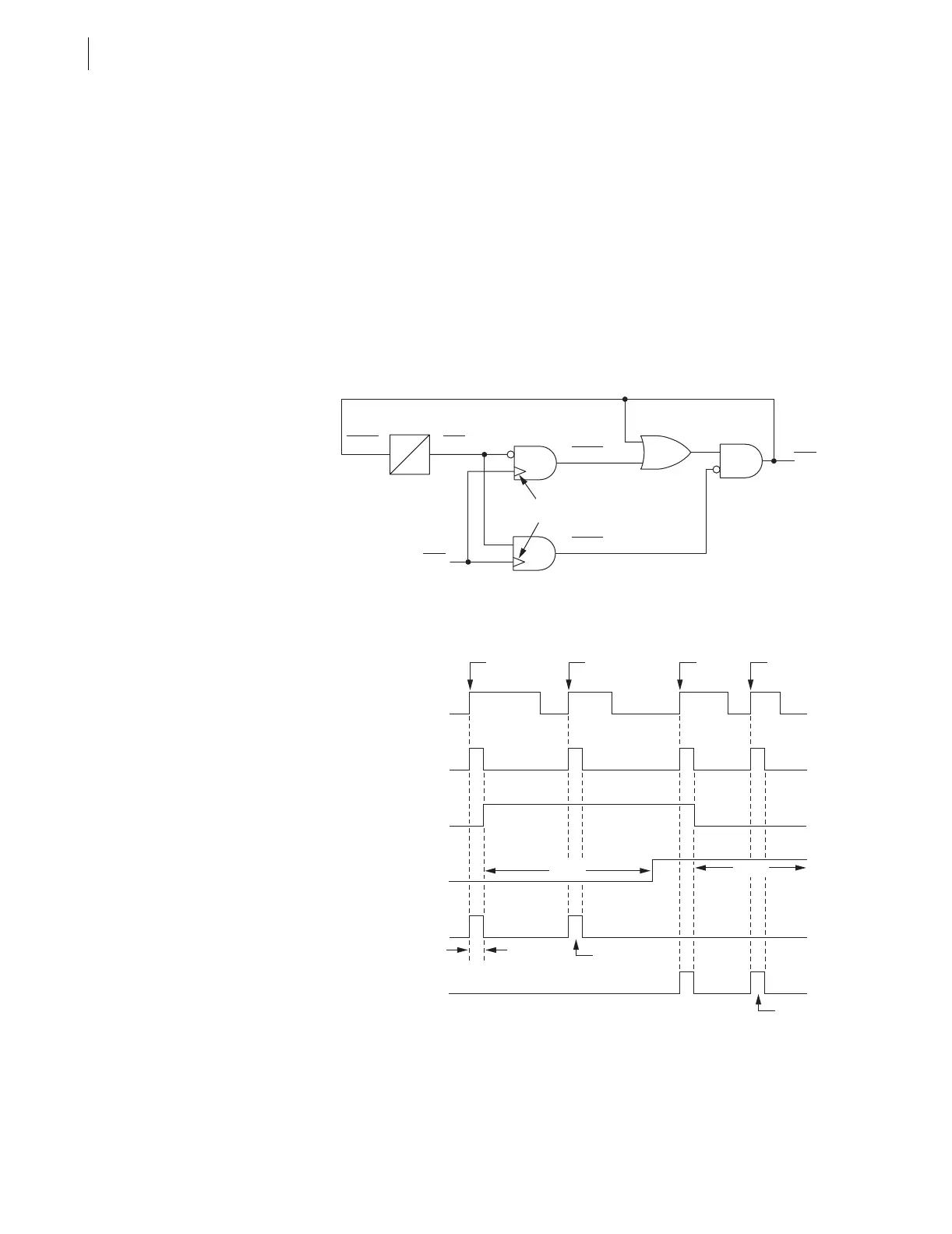
Another variation to the example application in Figure 7.13–Figure 7.15 that
adds more security is a timer with pickup/dropout times set the same (see
Figure 7.17 and Figure 7.18). Suppose that SV6PU and SV6DO are both set
to 300 cycles. Then the SV6T timer keeps the state of latch bit LT1 from being
able to be changed at a rate faster than once every 300 cycles (5 seconds).
Figure 7.17 Latch Control Switch (With Time Delay Feedback)
Controlled by a Single Input to Enable/Disable Reclosing
Figure 7.18 Latch Control Switch (With Time Delay Feedback)
Operation Time Line
LT1
IN104
(Set)
(Reset)
Rising Edge
Detect
SET1
RST1
SELOGIC
Setting
SELOGIC
Setting
SELOGIC
Setting
Relay
Word
Bit
Relay
Word
Bit
Relay
Word
Bit
SV6PU
SV6D0
SV6TSV6
RST1 = /IN104 * SV6T
/IN104
IN104
SET1 = /IN104 * !SV6T
Rising
Edge
One
Processing
Interval
SV6DO
SV6PU
Pulse 1 Pulse 2 Pulse 3 Pulse 4
Rising
Edge
Rising
Edge
No Effect
No Effect
Rising
Edge
SV6 = LT1
SV6T