7.7
Date Code 20060320 Instruction Manual SEL-311C Relay
Inputs, Outputs, Timers, and Other Control Logic
Local Control Switches
Local Control Switches
The local control switch feature of this relay replaces traditional
panel-mounted control switches. Operate the sixteen (16) local control
switches using the front-panel keyboard/display (see Section 11: Front-Panel
Interface (Only on Models With LCD)).
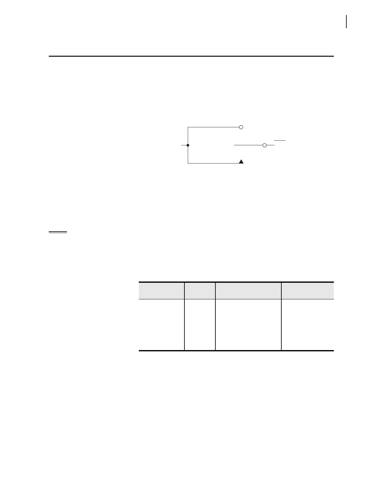
The switch representation in this figure is derived from the standard:
Graphics Symbols for Electrical and Electronics Diagrams IEEE Std 315-1975,
CSA Z99-1975, ANSI Y32.2-1975, 4.11 Combination Locking and Nonlocking Switch,
Item 4.11.1.
Figure 7.4 Local Control Switches Drive Local Bits LB1 Through LB16
The output of the local control switch in Figure 7.4 is a Relay Word bit LBn
(n = 1–16), called a local bit. The local control switch logic in Figure 7.4
repeats for each local bit LB1–LB16. Use these local bits in SEL
OGIC control
equations. For a given local control switch, the local control switch positions
are enabled by making corresponding label settings.
Note the first setting in Table 7.1 (NLBn) is the overall switch name setting.
Make each label setting through the serial port using the command SET T.
View these settings using the serial port command SHO T (see Section 9:
Setting the Relay and Section 10: Serial Port Communications and
Commands).
Local Control
Switch Types
Configure any local control switch as one of the following three switch types:
ON/OFF Switch
Local bit LBn is in either the ON (LBn = logical 1) or OFF (LBn = logical 0)
position.
Table 7.1 Correspondence Between
Local Control Switch Positions and Label Settings
Switch Position
Label
Setting
Setting Definition Logic State
not applicable NLBn Name of
Local Control Switch
not applicable
ON SLBn “Set” Local bit LBn logical 1
OFF CLBn “Clear” Local bit LBn logical 0
MOMENTARY PLBn “Pulse” Local bit LBn logical 1 for one
processing interval
Logical 1
LBn
(n = 1 through 16)
ON Position
(Maintained Logical 1
Position)
OFF Position
(Maintained Logical 0 Position)
MOMENTARY Position
(Logical 1 for One Processing Interval)
Relay
Word
Bit
NOTE: On SEL-311C relays without an
LCD, the Relay Word bits LB1–LB16 are
always = logical 0. (Local bit control is
not possible because there are no
front-panel buttons or displays on the
relay.)

 Loading...


