3.28
SEL-311C Relay Instruction Manual Date Code 20060320
Distance, Out-of-Step, Overcurrent, Voltage, Synchronism Check, and Frequency Elements
Instantaneous/Definite-Time Overcurrent Elements
Other SELOGIC control equation torque control settings may be set to provide
directional control. See Overcurrent Directional Control Provided by Torque
Control Settings on page 4.28.
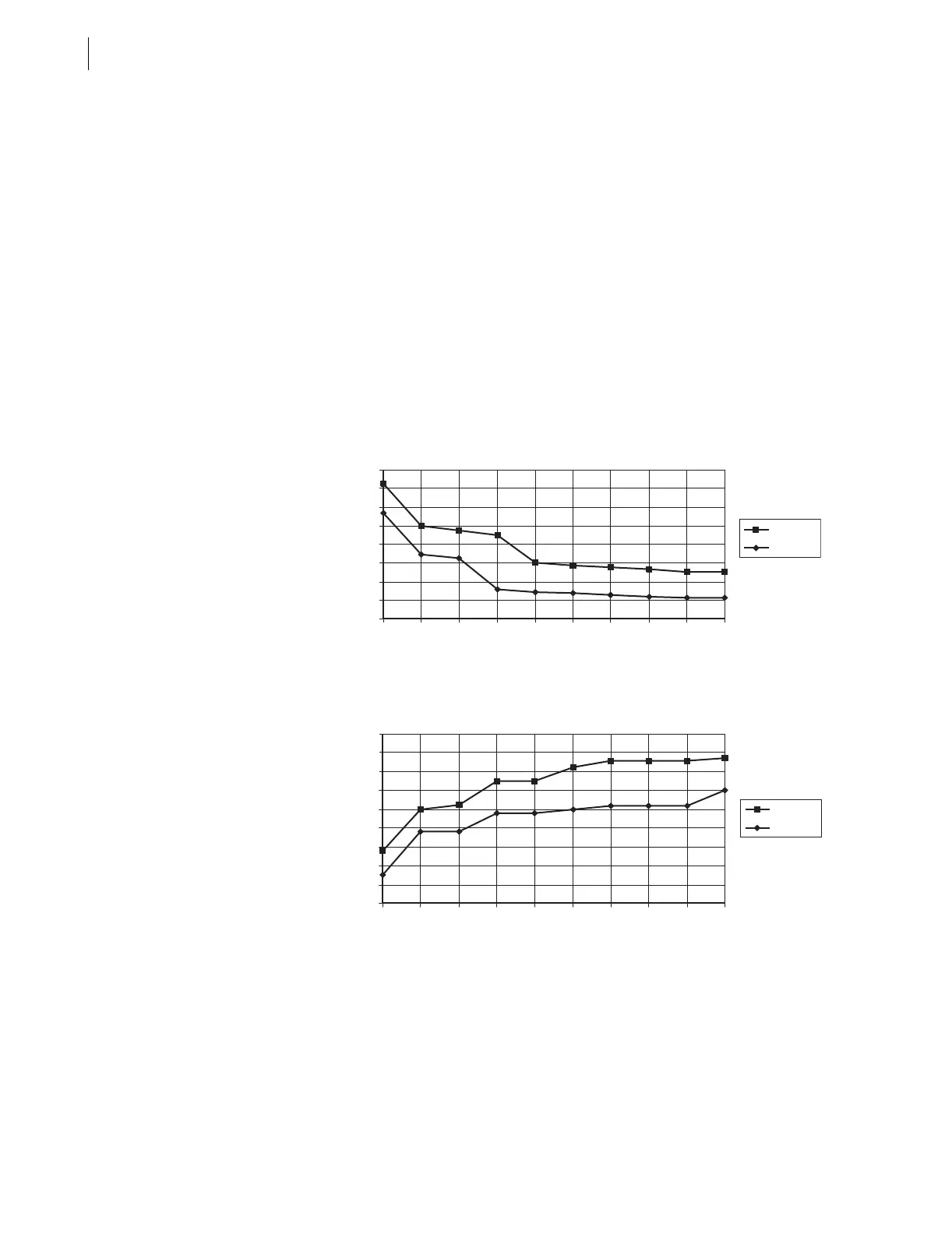
Pickup and Reset Time Curves
Figure 3.20 and Figure 3.21 show pickup and reset time curves applicable to
all nondirectional instantaneous overcurrent elements in the SEL-311C (60 Hz
or 50 Hz relays). These times do not include output contact operating time
and, thus, are accurate for determining element operation time for use in
internal SEL
OGIC control equations. Output contact pickup/dropout time is
typically 4 ms (0.25 cycle for a 60 Hz relay; 0.20 cycle for a 50 Hz relay).
If instantaneous overcurrent elements are made directional (with standard
directional elements such as 32QF), the pickup time curve in Figure 3.20 is
adjusted as follows:
multiples of pickup setting ≤ 4: add 0.25 cycle
multiples of pickup setting > 4: add 0.50 cycle
Figure 3.20 SEL-311C Nondirectional Instantaneous Overcurrent Element
Pickup Time Curve
Figure 3.21 SEL-311C Nondirectional Instantaneous Overcurrent Element
Reset Time Curve
Residual Ground
Instantaneous/
Definite-Time
Overcurrent Elements
Four levels of residual ground instantaneous/definite-time overcurrent
elements are available. The different levels are enabled with the E50G enable
setting, as shown in Figure 3.22.
All residual ground instantaneous/definite-time overcurrent elements are
available for use in any user-defined tripping or control scheme.
0
0.2
0.4
0.6
0.8
1
1.2
1.4
1.6
1.2 2 3 4 5 6 7 8 9 10
Applied Current (Multiples of Pickup Setting)
Pickup Time (Cycles)
Maximum
Minimum
0
0.2
0.4
0.6
0.8
1
1.2
1.4
1.6
1.8
1.2 2 3 4 5 6 7 8 9 10
Applied Current (Multiples of Pickup Setting)
Reset Time (Cycles)
Maximum
Minimum