7.17
Date Code 20060320 Instruction Manual SEL-311C Relay
Inputs, Outputs, Timers, and Other Control Logic
Latch Control Switches
If individual settings are changed for a setting group other than the active
setting group, there is no interruption of the latch bits (the relay is not
momentarily disabled).
If the individual settings change or active setting group change causes a
change in SEL
OGIC control equation settings SETn or RSTn (n = 1–16), the
retained states of the latch bits can be changed, subject to the newly enabled
settings SETn or RSTn.
Reset Latch Bits
for Active Setting
Group Change
If desired, the latch bits can be reset to logical 0 right after a setting group
change, using SEL
OGIC control equation setting RSTn (n = 1–16). Relay
Word bits SG1–SG6 indicate the active setting Group 1–6, respectively (see
Table 7.4).
For example, when setting Group 4 becomes the active setting group, latch bit
LT2 should be reset. Make the following SEL
OGIC control equation settings in
setting Group 4:
SV7 = SG4
RST2 = !SV7T + ...
[= NOT(SV7T) + ...]
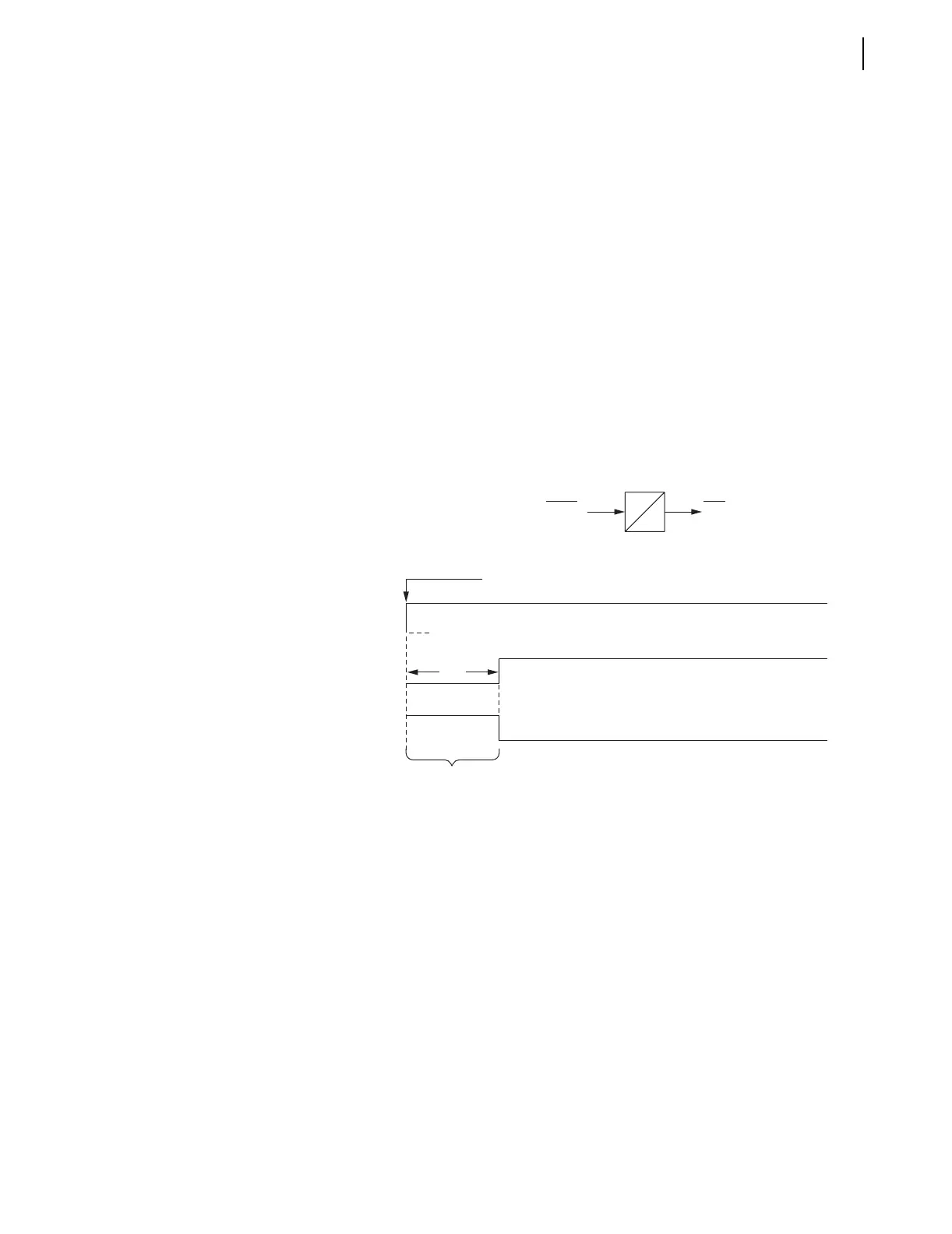
Figure 7.16 Time Line for Reset of Latch Bit LT2 After Active
Setting Group Change
In Figure 7.16, latch bit LT2 is reset (deasserted to logical 0) when reset
setting RST2 asserts to logical 1 for the short time right after setting Group 4
is activated. This logic can be repeated for other latch bits.
Make Latch
Control Switch
Settings With Care
The latch bit states are stored in nonvolatile memory so they can be retained
during power loss, settings change, or active setting group change. The
nonvolatile memory is rated for a finite number of “writes” for all cumulative
latch bit state changes. Exceeding the limit can result in an EEPROM self-test
failure. An average of 150 cumulative latch bit state changes per day can
be made for a 25-year relay service life.
This requires that SEL
OGIC control equation settings SETn and RSTn for
any given latch bit LTn be set with care. Settings SETn and RSTn cannot
result in continuous cyclical operation of latch bit LTn. Use timers to qualify
conditions set in settings SETn and RSTn. If any optoisolated inputs IN101–
SV7 = SG4
SV7T
RST2 = !SV7T
Setting Group 4 Activated
Latch Bit LT2
Reset to Logical 0
SV7PU
SV7 = SG4 SV7T
SV7PU = 3
SV7DO = 0
SV7PU
SV7D0
Relay
Word
Bit
SELOGIC
Setting