3.7
Date Code 20060320 Instruction Manual SEL-311C Relay
Distance, Out-of-Step, Overcurrent, Voltage, Synchronism Check, and Frequency Elements
Distance Elements
Mho Phase Distance Elements
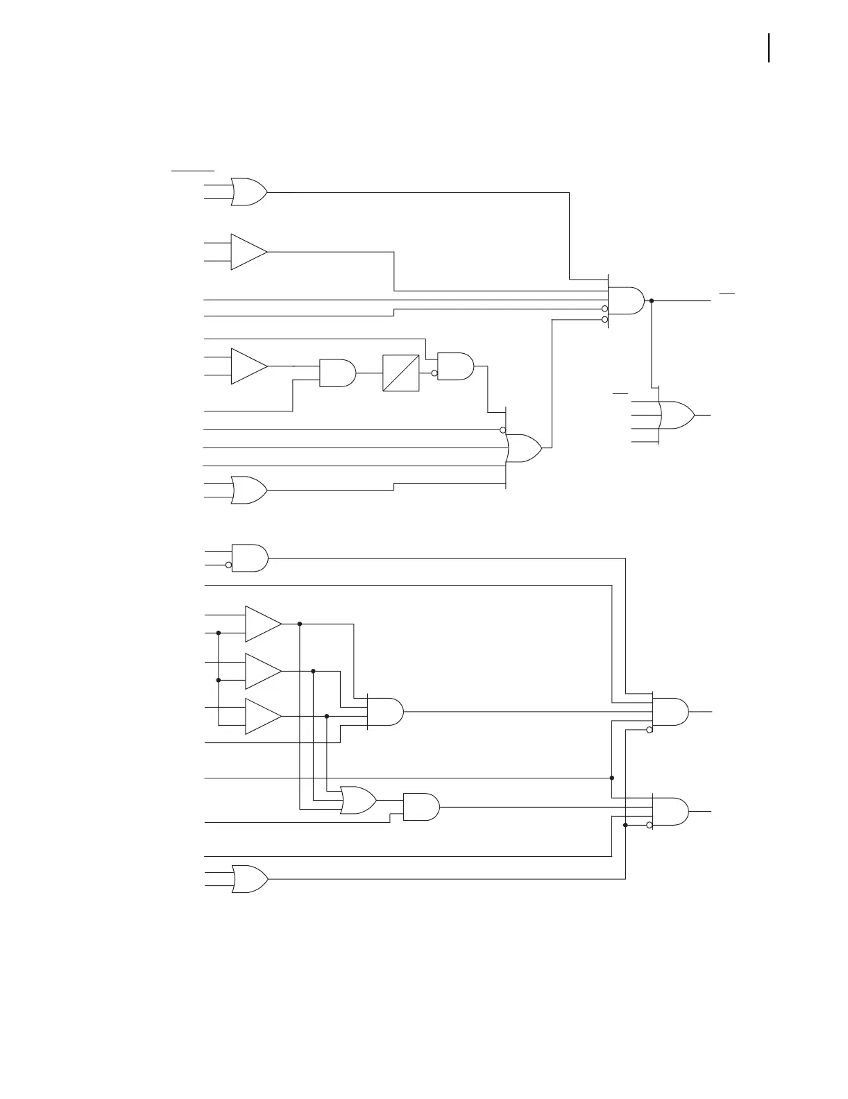
Note 1: mAB = A-Phase to B-Phase Distance Calculation, Z1P = Zone 1 Distance Setting, X1 = Zone 1 Extension u.
Note 2: ABC1 and PP1 are compensator distance element calculations. Zone 1 extension, if active, is included in this
calculation.
q From Figure 4.14; w from Figure 4.15; e from Figure 3.18; r from Figure 3.23; t from Figure 4.2; y from
Figure 4.1; u from Figure 3.15.
Figure 3.4 Zone 1 AB Phase Distance Logic
q 32QF
w F32P
(Internal Element)
|IAB|
50PP1
(Setting)
_
+
MAB1
Zone 1 Phase Distance Logic for AB Phase Pair. BC and CA Logic Is Similar.
See Note 1 mAB < Z1P • X1
t CVTBL
VPOLV
y ILOP
FSB
FSA
"C" in E21P
M1P
MBC1
MCA1
Relay
Word
Bits
Relay
Word
Bits
MABC1
MPP1
Relay
Word
Bits
(unless noted)
e OSB1
a2
(Setting)
r 50Q1
|I2|/|I1|
_
+
UBD
0
q 32QF
w F32P
(Internal Element)
MABC1
Zone 1 Compensator Distance Logic
|IAB|
50PP1
(Setting)
"C" in E21P
(Setting)
VPOLV
y ILOP
|IBC|
|ICA|
See Note 2 ABC1 < 0
(Calc)
See Note 2 PP1 < 0
(Calc)
MPP1
t CVTBL
_
+
_
+
_
+
OSB1