8.22
SEL-311C Relay Instruction Manual Date Code 20060320
Breaker Monitor and Metering Functions
Demand Metering
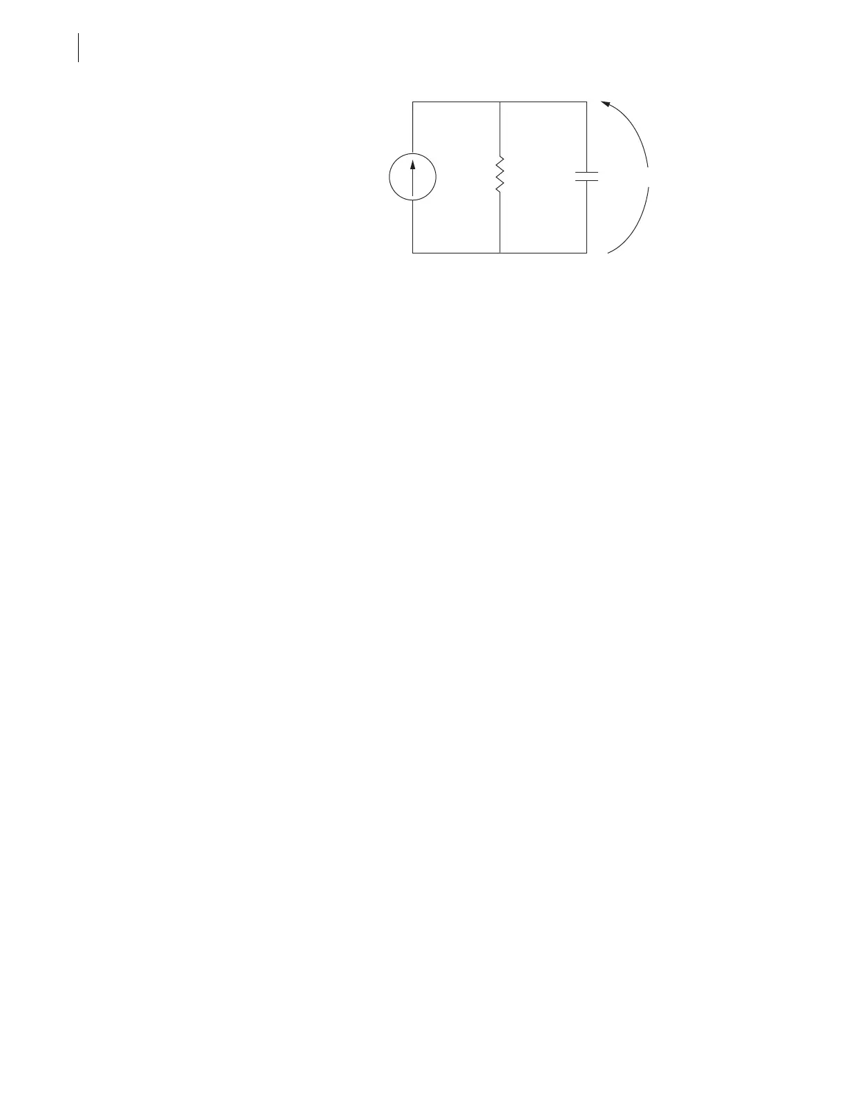
Figure 8.12 Current I
S
Applied to Parallel RC Circuit
In the analogy:
➤ Current I
S
in Figure 8.12 corresponds to the step current input
in Figure 8.11 (top).
➤ Voltage V
C
across the capacitor in Figure 8.12 corresponds to
the response of the thermal demand meter in Figure 8.11
(middle).
If current I
S
in Figure 8.12 has been at zero (I
S
= 0.0 per unit) for some time,
voltage V
C
across the capacitor in Figure 8.12 is also at zero (V
C
= 0.0 per
unit). If current I
S
is suddenly stepped up to some constant value (I
S
= 1.0 per
unit), voltage V
C
across the capacitor starts to rise toward the 1.0 per unit
value. This voltage rise across the capacitor is analogous to the response of the
thermal demand meter in Figure 8.11 (middle) to the step current input (top).
In general, just as voltage V
C
across the capacitor in Figure 8.12 cannot
change instantaneously, the thermal demand meter response cannot change
instantaneously for increasing or decreasing current. The thermal demand
meter response time is based on the demand meter time constant setting
DMTC (see Table 8.4). Note in Figure 8.11, the thermal demand meter
response (middle) is at 90 percent (0.9 per unit) of full applied value (1.0 per
unit) after a time period equal to setting DMTC = 15 minutes, referenced to
when the step current input is first applied.
The SEL-311C updates thermal demand values approximately every two
seconds.
Rolling Demand Meter Response (EDEM = ROL)
The response of the rolling demand meter in Figure 8.11 (bottom) to the step
current input (top) is calculated with a sliding time-window arithmetic average
calculation. The width of the sliding time-window is equal to the demand
meter time constant setting DMTC (see Table 8.4). Note in Figure 8.11, the
rolling demand meter response (bottom) is at 100 percent (1.0 per unit) of full
applied value (1.0 per unit) after a time period equal to setting DMTC = 15
minutes, referenced to when the step current input is first applied.
The rolling demand meter integrates the applied signal (e.g., step current)
input in five-minute intervals. The integration is performed approximately
every two seconds. The average value for an integrated five-minute interval is
derived and stored as a five-minute total. The rolling demand meter then
averages a number of the five-minute totals to produce the rolling demand
meter response. In the Figure 8.11 example, the rolling demand meter
averages the three latest five-minute totals because setting DMTC = 15 (15/5
= 3). The rolling demand meter response is updated every five minutes, after a
new five-minute total is calculated.
V
C
+
—
R
C
I
S



 To Next Page