3.42
SEL-311C Relay Instruction Manual Date Code 20060320
Distance, Out-of-Step, Overcurrent, Voltage, Synchronism Check, and Frequency Elements
Voltage Elements
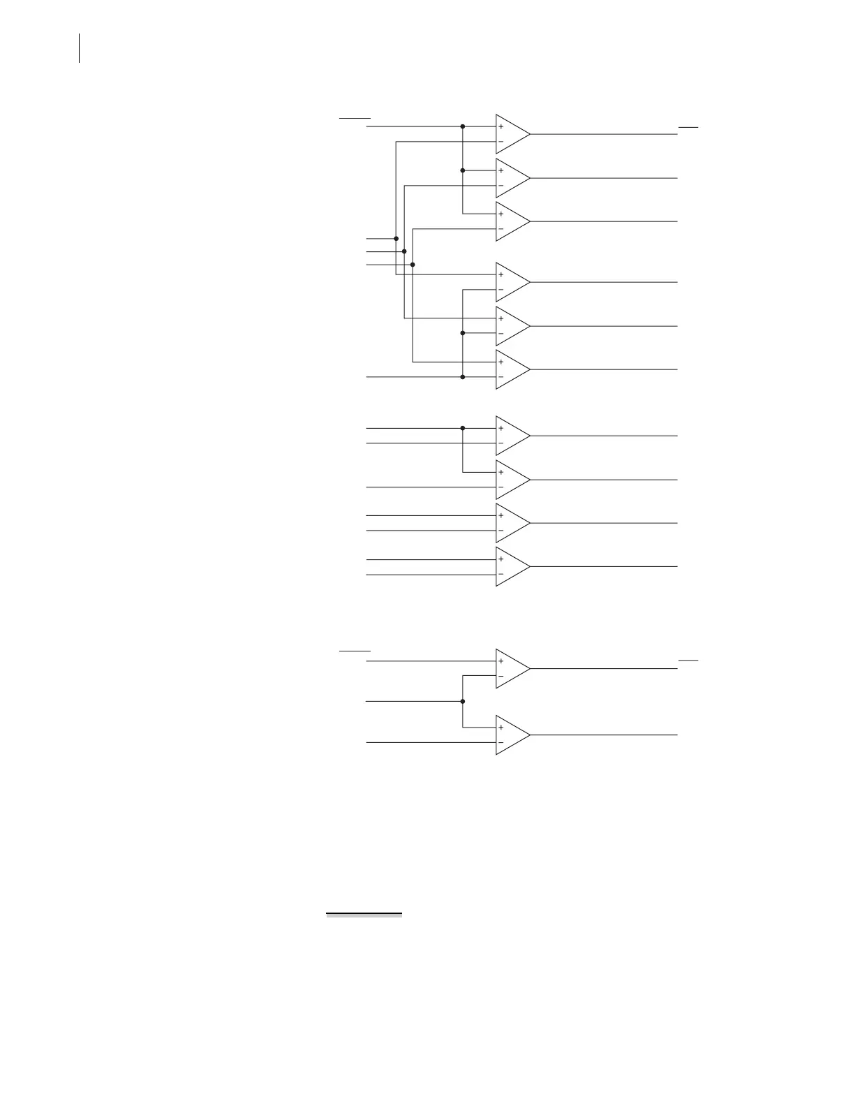
Figure 3.28 Phase-to-Phase and Sequence Voltage Elements
Figure 3.29 Channel V
S
Voltage Elements
Voltage Element
Operation
Note that the voltage elements in Table 3.14 and Figure 3.27–Figure 3.29 are
a combination of “undervoltage” (Device 27) and “overvoltage” (Device 59)
type elements. Undervoltage elements (Device 27) assert when the operating
voltage goes below the corresponding pickup setting. Overvoltage elements
(Device 59) assert when the operating voltage goes above the corresponding
pickup setting.
EXAMPLE 3.1 Undervoltage Element Operation
Refer to Figure 3.27 (top of the figure).
Pickup setting 27P is compared to the magnitudes of the individual
phase voltages V
A
, V
B
, and V
C
. The logic outputs in Figure 3.27 are
the following Relay Word bits:
27A = 1 (logical 1), if V
A
< pickup setting 27P
27A = 0 (logical 0), if V
A
≥ pickup setting 27P
27AB
27BC
27CA
59N1
59N2
59Q
59V1
59AB
59BC
59CA
27PP
59PP
|3V
0
|
59N1P
59N2P
|V
2
|
59QP
|V
1
|
59V1P
|V
AB
|
|V
BC
|
|V
CA
|
Settings/
Voltages
Relay
Word
Bits
27S
59S
27SP
|V
S
|
59SP
Settings/
Voltages
Relay
Word
Bits