11.11
Date Code 20060320 Instruction Manual SEL-311C Relay
Front-Panel Interface (Only on Models With LCD)
Functions Unique to the Front-Panel Interface
See Local Control Switches on page 7.7 for details on how local bit outputs
LB3 and LB4 are set in SEL
OGIC control equation settings to respectively trip
and close a circuit breaker.
Local Control State Retained When Relay De-energized
Local bit states are stored in nonvolatile memory, so when power to the relay
is turned off, the local bit states are retained.
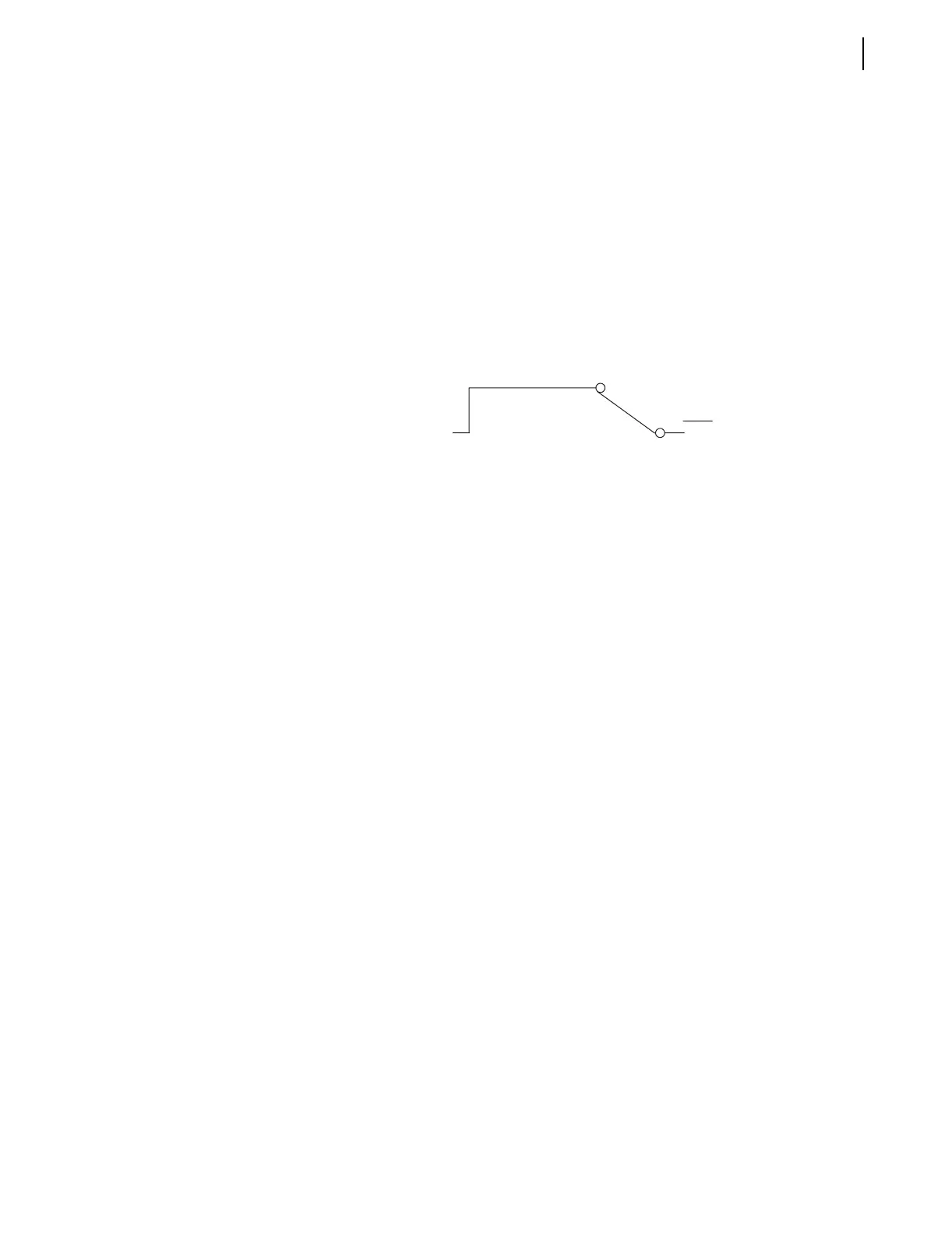
For example, suppose the local control switch with local bit output LB1 is
configured as an ON/OFF type switch (see Figure 11.5). Additionally,
suppose it is used to enable/disable reclosing. If local bit LB1 is at logical 1,
reclosing is enabled:
If power to the relay is turned off and then turned on again, local bit LB1
remains at logical 1, and reclosing is still enabled. This is similar to a
traditional panel, where enabling/disabling of reclosing and other functions is
accomplished by panel-mounted switches. If dc control voltage to the panel is
lost and then restored again, the switch positions are still in place. If the
reclosing switch is in the enable position (switch closed) before the power
outage, it will be in the same position after the outage when power is restored.
Logical 1
LB1
ENABLE
RECLOSER
DISABLE
(Logical 0)
Relay
Word
Bit



 To Next Page