14.55
Date Code 20060320 Instruction Manual SEL-311C Relay
Application Settings for SEL-221 Series Relays
SEL-2PG10 to SEL-311C Settings Conversion Guide
Z1ANG
Z0MAG
Z0ANG
LL = LL
APP None
Z1P Mho Phase Distance Elements
on page 3.1
where:
Z1PD = PTMR Zone Time Delay Elements on
page 3.20
50G1P = 67NIP/CTR Residual Ground Instantaneous/
Definite-Time Overcurrent Ele-
ments on page 3.28
(SV1 = 50G1) = 67NIP (Nondirectional)
67G1D = GTMR (Directional)
SV1T = GTMR (Nondirectional)
51GP = 67NP/CTR Residual Ground Time-Overcur-
rent Element on page 3.36
51GC
U1
b
U2
U3
U4
= 67NC
= 1
= 2
= 3
= 4
51GTD = 67NTD
51GTC = 67NC (51GTC is an SEL-311C
SEL
OGIC setting.)
(=1 = Nondirectional)
(= 32GF = Torque Controlled)
ORDER Directional Control for Ground
Distance and Residual Ground
Overcurrent Elements on
page 4.9
Q= 32QE
V= 32VE
I= 32IE
a
SEL-311C phase-to-phase fault detector settings (50PP1) is set to its minimum value and hidden. This corresponds to SEL-2PG10 setting
50L.
b
Curve U1 in the SEL-311C is slightly different from curve 1 in the SEL-2PG10. Time dial adjustments may be necessary.
Table 14.32 SEL-311C Settings Calculated From SEL-2PG10 Settings (Sheet 2 of 2)
SEL-311C
Setting
a
Calculated From SEL-2PG10 Settings
SEL-311C Instruction
Manual Section
SEL-2PG10 Instruction
Manual Section
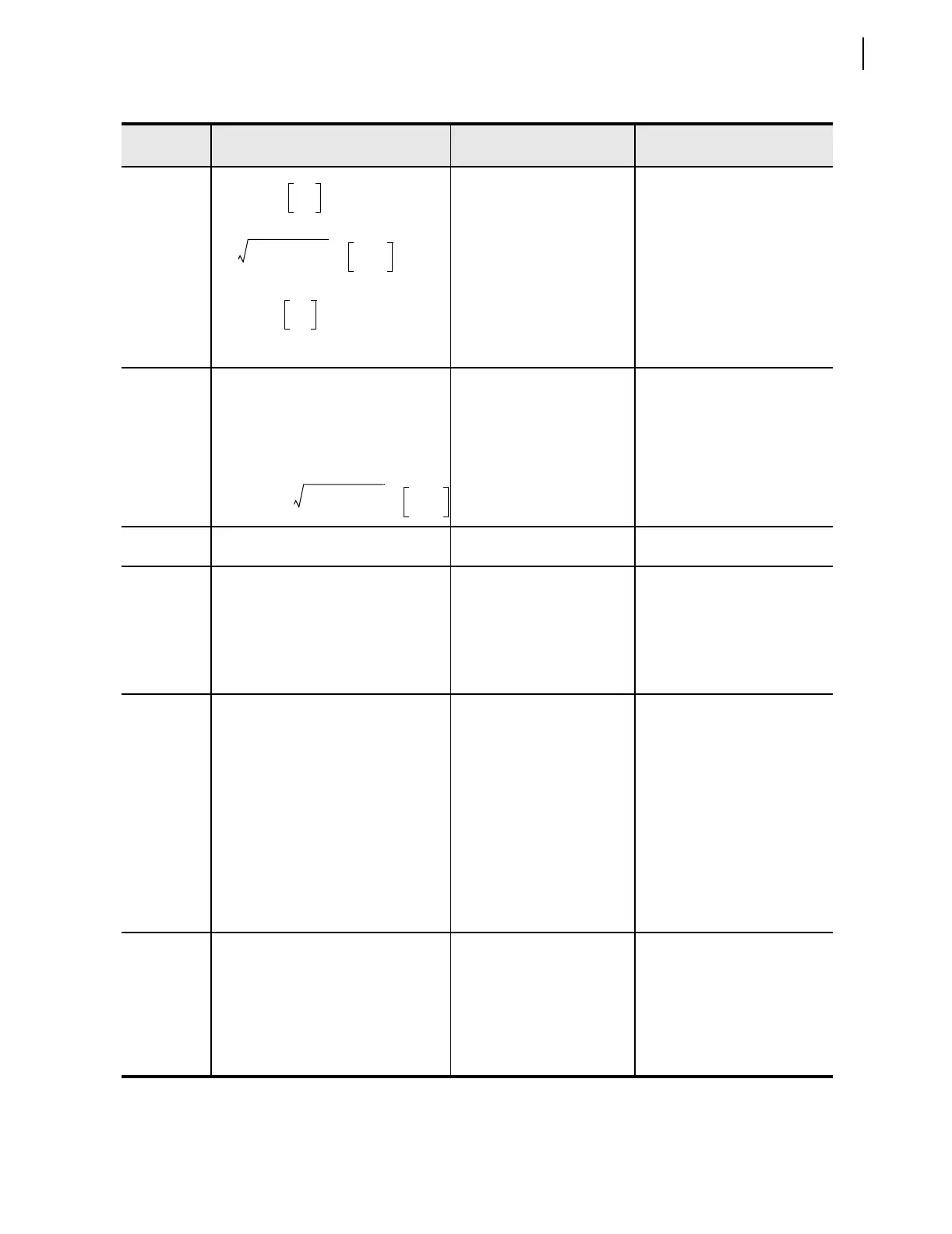
Arc tan
X1
R1
-------
= (degrees) = MTA
R0
2
X0
2
+()=
CTR
PTR
------------
•
Arc tan
X0
R0
-------
= (degrees)
Z%
100
---------
Z1MAG• =
Z1MAG R1
2
X1
2
+()=
CTR
PTR
------------
•



 To Next Page