4.9
Date Code 20120126 Instruction Manual SEL-2032 Communications Processor
SELOGIC Control Equations
Outputs
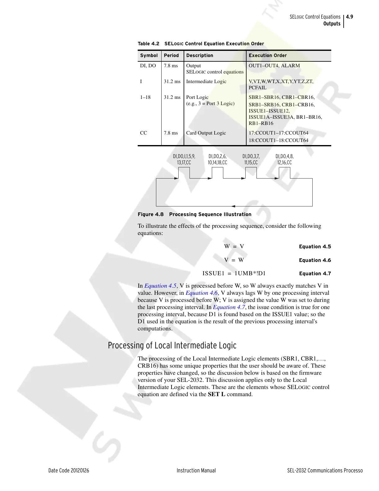
Figure 4.8 Processing Sequence Illustration
To illustrate the effects of the processing sequence, consider the following
equations:
Equation 4.5
Equation 4.6
Equation 4.7
In Equation 4.5, V is processed before W, so W always exactly matches V in
value. However, in Equation 4.6, V always lags W by one processing interval
because V is processed before W; V is assigned the value W was set to during
the last processing interval. In Equation 4.7, the issue condition is true for one
processing interval, because D1 is found based on the ISSUE1 value; so the
D1 used in the equation is the result of the previous processing interval's
computations.
Processing of Local Intermediate Logic
The processing of the Local Intermediate Logic elements (SBR1, CBR1,…,
CRB16) has some unique properties that the user should be aware of. These
properties have changed, so the discussion below is based on the firmware
version of your SEL-2032. This discussion applies only to the Local
Intermediate Logic elements. These are the elements whose SEL
OGIC control
equation are defined via the SET L command.
Tab l e 4 . 2 S EL OGIC Control Equation Execution Order
Symbol Period Description Execution Order
DI, DO 7.8 ms Output
SELOGIC control equations
OUT1–OUT4, ALARM
I 31.2 ms Intermediate Logic V,VT,W,WT,X,XT,Y,YT,Z,ZT,
PCFAIL
1–18 31.2 ms Port Logic
(e.g., 3 = Port 3 Logic)
SBR1–SBR16, CBR1–CBR16,
SRB1–SRB16, CRB1–CRB16,
ISSUE1–ISSUE12,
ISSUE1A–ISSUE3A, BR1–BR16,
RB1–RB16
CC 7.8 ms Card Output Logic 17:CCOUT1–17:CCOUT64
18:CCOUT1–18:CCOUT64
DI,DO,I,1,5,9,
13,17,CC
DI,DO,2,6,
10,14,18,CC
DI,DO,3,7,
11,15,CC
DI,DO,4,8,
12,16,CC
Courtesy of NationalSwitchgear.com