2.16
SEL-2032 Communications Processor Instruction Manual Date Code 20120126
Installation
Getting Started
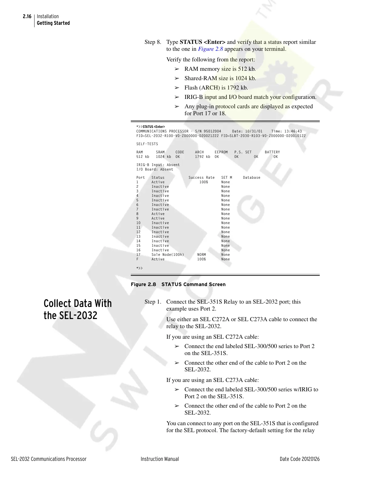
Step 8. Type STATUS <Enter> and verify that a status report similar
to the one in Figure 2.8 appears on your terminal.
Verify the following from the report:
➢ RAM memory size is 512 kb.
➢ Shared-RAM size is 1024 kb.
➢ Flash (ARCH) is 1792 kb.
➢ IRIG-B input and I/O board match your configuration.
➢ Any plug-in protocol cards are displayed as expected
for Port 17 or 18.
*>>STATUS <Enter>
COMMUNICATIONS PROCESSOR - S/N 95012004 Date: 10/31/01 Time: 13:46:43
FIDSEL-2032-R100-V0-Z000000-D20021222 FIDSLBT-2030-R103-V0-Z000000-D20010122
SELF-TESTS
RAM SRAM CODE ARCH EEPROM P.S. SET BATTERY
512 kb 1024 kb OK 1792 kb OK OK OK OK
IRIG-B Input: Absent
I/O Board: Absent
Port Status Success Rate SET M Database
1 Active 100% None
2 Inactive None
3 Inactive None
4 Inactive None
5 Inactive None
6 Inactive None
7 Inactive None
8 Active None
9 Active None
10 Inactive None
11 Inactive None
12 Inactive None
13 Inactive None
14 Inactive None
15 Inactive None
16 Inactive None
17 Sole Node(100h) NORM None
F Active 100% None
*>>
Figure 2.8 STATUS Command Screen
Collect Data With
the SEL-2032
Step 1. Connect the SEL-351S Relay to an SEL-2032 port; this
example uses Port 2.
Use either an SEL C272A or SEL C273A cable to connect the
relay to the SEL-2032.
If you are using an SEL C272A cable:
➢ Connect the end labeled SEL-300/500 series to Port 2
on the SEL-351S.
➢ Connect the other end of the cable to Port 2 on the
SEL-2032.
If you are using an SEL C273A cable:
➢ Connect the end labeled SEL-300/500 series w/IRIG to
Port 2 on the SEL-351S.
➢ Connect the other end of the cable to Port 2 on the
SEL-2032.
You can connect to any port on the SEL-351S that is configured
for the SEL protocol. The factory-default setting for the relay
Courtesy of NationalSwitchgear.com