2.4
SEL-2032 Communications Processor Instruction Manual Date Code 20120126
Installation
Mounting and Connections
Power
Connections
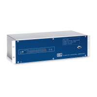
The terminals labeled “POWER” on the rear panel must be connected to a
power source that matches the power supply (POW SUP) characteristics
specified on the rear-panel nameplate of your SEL-2032. If you provide a dc
power source, you must connect the source with the proper polarity as
indicated by the “+” and “” labels on the power connector. The SEL-2032
internal power supply has very low power consumption and a wide voltage
tolerance. See Specifications on page 1.28 for complete power supply
specifications.
Alarm Contact
Connection
The SEL-2032 includes an alarm output contact connected to pins 1 and 3 on
the rear panel. At the factory, the alarm contact is configured to be closed for
an alarm condition, and open for normal operation. This is a Form B contact
because it is closed when there is no power. To invert the alarm output to close
under normal conditions, change soldered jumper, JMP3, on the main board to
select Form A contact usage. See Table 2.1 and Figure 2.4 for jumper settings.
The alarm contact asserts when no power is connected to the SEL-2032, the
power supply fails, or self-test diagnostics detect a failure. Self-test diagnostic
failures include memory failures, power supply failures, and invalid setting
failures. See STATUS on page 8.21 for a discussion on these failures. With the
default ALARM setting (Global Settings), the alarm contact is pulsed when
Level 2 communication is accessed, or when an SEL-2032 setting change is
accepted.
The ALARM LED illuminates whenever the alarm contact asserts.
IRIG-B
Input Connection
The SEL-2032 accepts a modulated or demodulated IRIG-B signal through a
rear-panel BNC connector labeled “MODULATED/DEMODULATED
IRIG-B IN.” An internal setting selects between modulated and demodulated
IRIG-B (Global Settings). The factory-default setting is demodulated IRIG-B
time input.
The SEL-2032 can also accept IRIG-B on the IRIG-B pins of Port 15. By
default, the IRIG on Port 15 is configured as an output, but it can also be used
as a demodulated IRIG-B input. To do this, set JMP1 and JMP2 in the 2-3
position. Also, the IRIG setting must be set to demodulated. See Table 2.1 and
Figure 2.4 for the main-board jumper positions for setting-up the Port 15
IRIG-B.
Use a modulated IRIG-B signal for the input to the SEL-2032 if it is available.
The modulated signal is isolated by a transformer. The demodulator in the
SEL-2032 includes automatic gain control. You can use a demodulated signal,
but it may not be adequate if the cable to the source is too long.
An internal element asserts in the SEL-2032 Global database region when an
adequate IRIG-B input signal is received. If no external IRIG-B input signal is
applied, the SEL-2032 generates an IRIG-B signal. The SEL-2032 includes an
internal battery-backed clock/calendar that maintains correct time with or
without external power.
IRIG-B Output
Connection
The SEL-2032 distributes a demodulated IRIG-B output signal through all of
its 16 rear ports. You can use this feature to synchronize any type of device,
such as a relay, fault recorder, or meter that can decode the IRIG-B signal; you
need only to connect the device to the desired SEL-2032 rear serial
communication port using a special cable designed for both communication
and IRIG-B signal. The IRIG-B signal is on pins 4 and 6 of the 9-pin,
subminiature “D” connector (see Figure 2.1 and Tabl e 2.3).
Courtesy of NationalSwitchgear.com