3.10
SEL-2032 Communications Processor Instruction Manual Date Code 20120126
Job Done Examples
Example 2: Using the SEL-2032 as a Port Switch
Verify and
Test All
Communication
Paths
The remainder of this example verifies proper communication with the
SEL-251 Relays attached to each port of the SEL-2032.
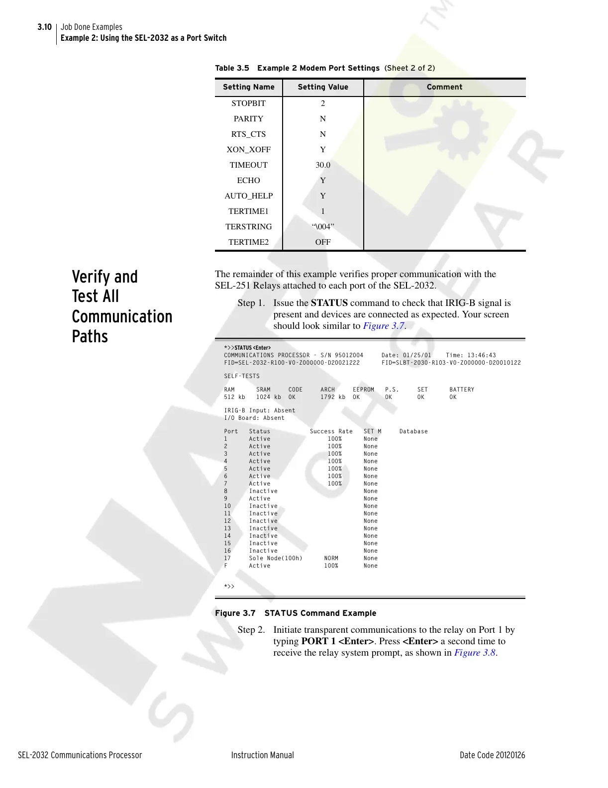
Step 1. Issue the STATUS command to check that IRIG-B signal is
present and devices are connected as expected. Your screen
should look similar to Figure 3.7.
*>>STATUS <Enter>
COMMUNICATIONS PROCESSOR - S/N 95012004 Date: 01/25/01 Time: 13:46:43
FID=SEL-2032-R100-V0-Z000000-D20021222 FID=SLBT-2030-R103-V0-Z000000-D20010122
SELF-TESTS
RAM SRAM CODE ARCH EEPROM P.S. SET BATTERY
512 kb 1024 kb OK 1792 kb OK OK OK OK
IRIG-B Input: Absent
I/O Board: Absent
Port Status Success Rate SET M Database
1 Active 100% None
2 Active 100% None
3 Active 100% None
4 Active 100% None
5 Active 100% None
6 Active 100% None
7 Active 100% None
8 Inactive None
9 Active None
10 Inactive None
11 Inactive None
12 Inactive None
13 Inactive None
14 Inactive None
15 Inactive None
16 Inactive None
17 Sole Node(100h) NORM None
F Active 100% None
*>>
Figure 3.7 STATUS Command Example
Step 2. Initiate transparent communications to the relay on Port 1 by
typing PORT 1 <Enter>. Press <Enter> a second time to
receive the relay system prompt, as shown in Figure 3.8.
STOPBIT 2
PARIT Y N
RTS_CTS N
XON_XOFF Y
TIMEOUT 30.0
ECHO Y
AUTO_HELP Y
TERTIME1 1
TERSTRING “\004”
TERTIME2 OFF
Table 3.5 Example 2 Modem Port Settings (Sheet 2 of 2)
Setting Name Setting Value Comment
Courtesy of NationalSwitchgear.com