6.9
Date Code 20120126 Instruction Manual SEL-2032 Communications Processor
Database
Region Descriptions
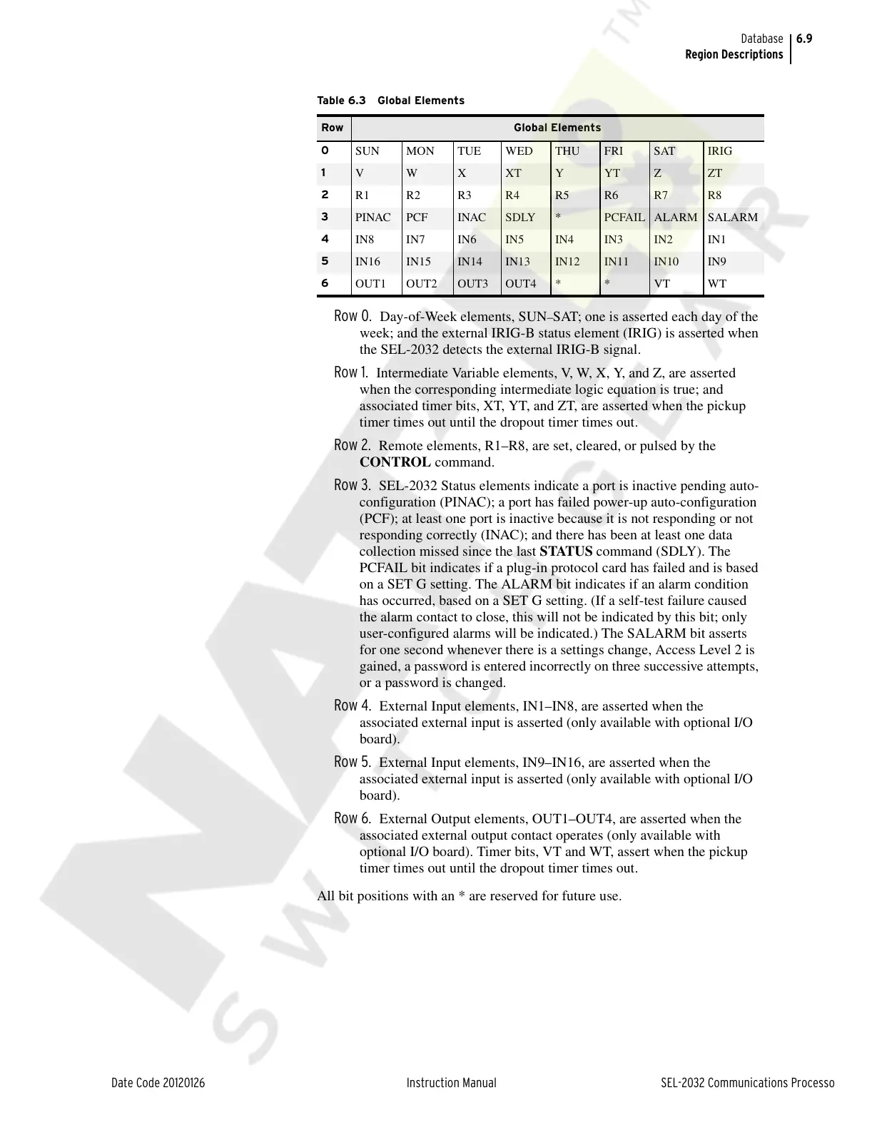
Row 0. Day-of-Week elements, SUN–SAT; one is asserted each day of the
week; and the external IRIG-B status element (IRIG) is asserted when
the SEL-2032 detects the external IRIG-B signal.
Row 1. Intermediate Variable elements, V, W, X, Y, and Z, are asserted
when the corresponding intermediate logic equation is true; and
associated timer bits, XT, YT, and ZT, are asserted when the pickup
timer times out until the dropout timer times out.
Row 2. Remote elements, R1–R8, are set, cleared, or pulsed by the
CONTROL command.
Row 3. SEL-2032 Status elements indicate a port is inactive pending auto-
configuration (PINAC); a port has failed power-up auto-configuration
(PCF); at least one port is inactive because it is not responding or not
responding correctly (INAC); and there has been at least one data
collection missed since the last STATUS command (SDLY). The
PCFAIL bit indicates if a plug-in protocol card has failed and is based
on a SET G setting. The ALARM bit indicates if an alarm condition
has occurred, based on a SET G setting. (If a self-test failure caused
the alarm contact to close, this will not be indicated by this bit; only
user-configured alarms will be indicated.) The SALARM bit asserts
for one second whenever there is a settings change, Access Level 2 is
gained, a password is entered incorrectly on three successive attempts,
or a password is changed.
Row 4. External Input elements, IN1–IN8, are asserted when the
associated external input is asserted (only available with optional I/O
board).
Row 5. External Input elements, IN9–IN16, are asserted when the
associated external input is asserted (only available with optional I/O
board).
Row 6. External Output elements, OUT1–OUT4, are asserted when the
associated external output contact operates (only available with
optional I/O board). Timer bits, VT and WT, assert when the pickup
timer times out until the dropout timer times out.
All bit positions with an * are reserved for future use.
Tab l e 6 . 3 Gl o ba l E le m e nt s
Row Global Elements
0
SUN MON TUE WED THU FRI SAT IRIG
1
V W X XT Y YT Z ZT
2
R1 R2 R3 R4 R5 R6 R7 R8
3
PINAC PCF INAC SDLY * PCFAIL ALARM SALARM
4
IN8 IN7 IN6 IN5 IN4 IN3 IN2 IN1
5
IN16 IN15 IN14 IN13 IN12 IN11 IN10 IN9
6
OUT1 OUT2 OUT3 OUT4 * * VT WT
Courtesy of NationalSwitchgear.com