2.6
SEL-2032 Communications Processor Instruction Manual Date Code 20120126
Installation
Mounting and Connections
Port Isolators
SEL offers a data-line-powered isolator for use with EIA-232 ports and
metallic communication cables. The SEL-2910 Port Isolator also isolates
IRIG-B time code inputs on the same communication port. These isolators
break cable ground loops and are useful in existing applications of metallic
cables in switchgear. SEL does not recommend using port isolators for circuits
outside the control house. Fiber should be used in such applications. Refer to
SEL Application Guide AG2001-06, Avoiding Magnetic Induction Issues in
Communication Cabling, for detailed information.
Fiber-Optic
Cables
A benefit of applying the SEL-2032 is that as the hub of a star topology, it
enables low cost, point-to-point fiber-optic connections. The SEL-2800 family
of Fiber-Optic Transceivers connects directly to the serial port connectors on
the rear of the SEL-2032. Fiber-optic links improve safety by isolating the
equipment from hazardous and damaging ground-potential rise, eliminate
instrumentation system ground-loop problems, reduce susceptibility to RFI
and EMI, and allow longer signal paths than metallic EIA-232 connections.
Communication
Cables
Several of the most popular SEL communication cables available for your use
with the SEL-2032 are listed in Table 2 .4. For a complete list of SEL cables
and recommended applications, see the SEL-5801 Cable Selector software
available on the SEL Web site. Using an improper cable can cause numerous
problems, so you must be sure to specify the proper cable for the application.
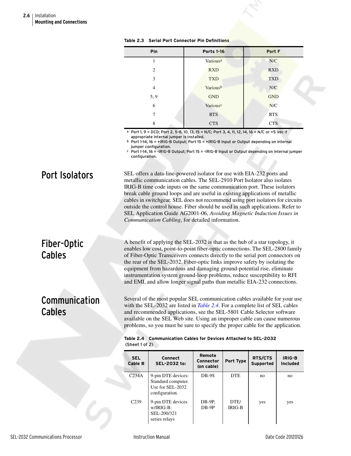
Table 2.3 Serial Port Connector Pin Definitions
Pin Ports 1–16 Port F
1Various
a
a
Port 1, 9 = DCD; Port 2, 5-8, 10, 13, 15 = N/C; Port 3, 4, 11, 12, 14, 16 = N/C or +5 Vdc if
appropriate internal jumper is installed.
N/C
2RXDRXD
3TXDTXD
4 Various
b
b
Port 1-14, 16 = +IRIG-B Output; Port 15 = +IRIG-B Input or Output depending on internal
jumper configuration.
N/C
5, 9 GND GND
6Various
c
c
Port 1-14, 16 = -IRIG-B Output; Port 15 = -IRIG-B Input or Output depending on internal jumper
configuration.
N/C
7RTSRTS
8CTSCTS
Table 2.4 Communication Cables for Devices Attached to SEL-2032
(Sheet 1 of 2)
SEL
Cable #
Connect
SEL-2032 to:
Remote
Connector
(on cable)
Port Type
RTS/CTS
Supported
IRIG-B
Included
C234A 9-pin DTE devices:
Standard computer.
Use for SEL-2032
configuration.
DB-9S DTE no no
C239 9-pin DTE devices
w/IRIG-B:
SEL-200/321
series relays
DB-9P,
DB-9P
DTE/
IRIG-B
yes yes
Courtesy of NationalSwitchgear.com