8.4
SEL-2032 Communications Processor Instruction Manual Date Code 20120126
Serial Port Communications and Commands
Command Set
2ACCESS
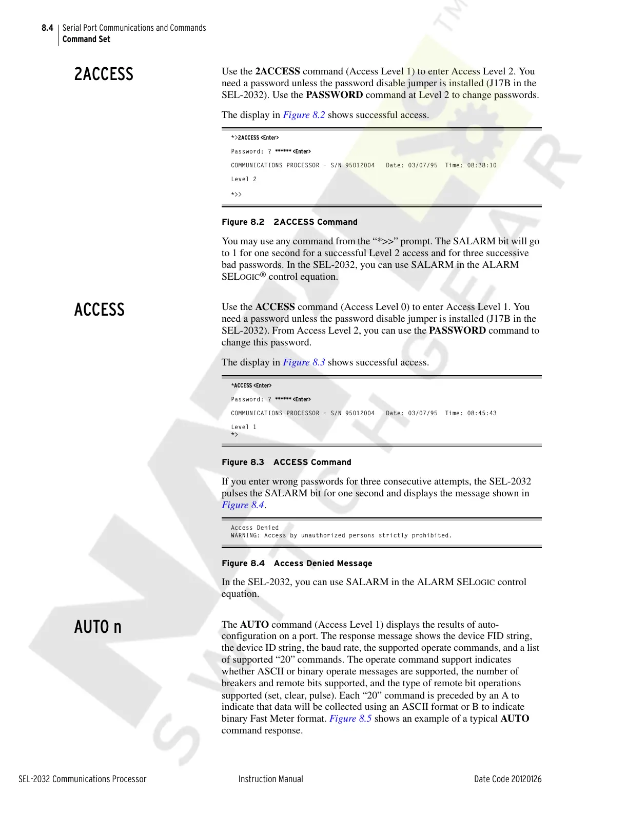
Use the 2ACCESS command (Access Level 1) to enter Access Level 2. You
need a password unless the password disable jumper is installed (J17B in the
SEL-2032). Use the PAS SWORD command at Level 2 to change passwords.
The display in Figure 8.2 shows successful access.
*>2ACCESS <Enter>
Password: ? ****** <Enter>
COMMUNICATIONS PROCESSOR - S/N 95012004 Date: 03/07/95 Time: 08:38:10
Level 2
*>>
Figure 8.2 2ACCESS Command
You may use any command from the “*>>” prompt. The SALARM bit will go
to 1 for one second for a successful Level 2 access and for three successive
bad passwords. In the SEL-2032, you can use SALARM in the ALARM
SEL
OGIC
®
control equation.
ACCESS
Use the ACCESS command (Access Level 0) to enter Access Level 1. You
need a password unless the password disable jumper is installed (J17B in the
SEL-2032). From Access Level 2, you can use the PASSWORD command to
change this password.
The display in Figure 8.3 shows successful access.
*ACCESS <Enter>
Password: ? ****** <Enter>
COMMUNICATIONS PROCESSOR - S/N 95012004 Date: 03/07/95 Time: 08:45:43
Level 1
*>
Figure 8.3 ACCESS Command
If you enter wrong passwords for three consecutive attempts, the SEL-2032
pulses the SALARM bit for one second and displays the message shown in
Figure 8.4.
Access Denied
WARNING: Access by unauthorized persons strictly prohibited.
Figure 8.4 Access Denied Message
In the SEL-2032, you can use SALARM in the ALARM SELOGIC control
equation.
AUTO n
The AUTO command (Access Level 1) displays the results of auto-
configuration on a port. The response message shows the device FID string,
the device ID string, the baud rate, the supported operate commands, and a list
of supported “20” commands. The operate command support indicates
whether ASCII or binary operate messages are supported, the number of
breakers and remote bits supported, and the type of remote bit operations
supported (set, clear, pulse). Each “20” command is preceded by an A to
indicate that data will be collected using an ASCII format or B to indicate
binary Fast Meter format. Figure 8.5 shows an example of a typical AUTO
command response.
Courtesy of NationalSwitchgear.com