7.37
Date Code 20120126 Instruction Manual SEL-2032 Communications Processor
Settings
Global (SET G) Settings
Global settings include primarily the intermediate logic and optional output
contact logic available in the SEL-2032. Table 7.11 lists all Global settings
and their description strings. You should use SET G to modify and SHO G to
view these settings.
Each of the five intermediate logic variables (V, W, X, Y, and Z) described in
Table 7.11 has corresponding generic pickup/dropout timers. For the output of
a timer to be asserted, its input must first be asserted for the pickup time. Once
a timer is asserted, for its output to be deasserted, its input must be deasserted
for the dropout time. If an I/O board is installed, you may define conditions
that assert outputs on the board.
You define the logic elements using SEL
OGIC control equations and set their
timers using the SET G command. For a complete discussion of these
equations, see Section 4: SEL
OGIC Control Equations.
Table 7.11 includes a complete description of the SET G settings.
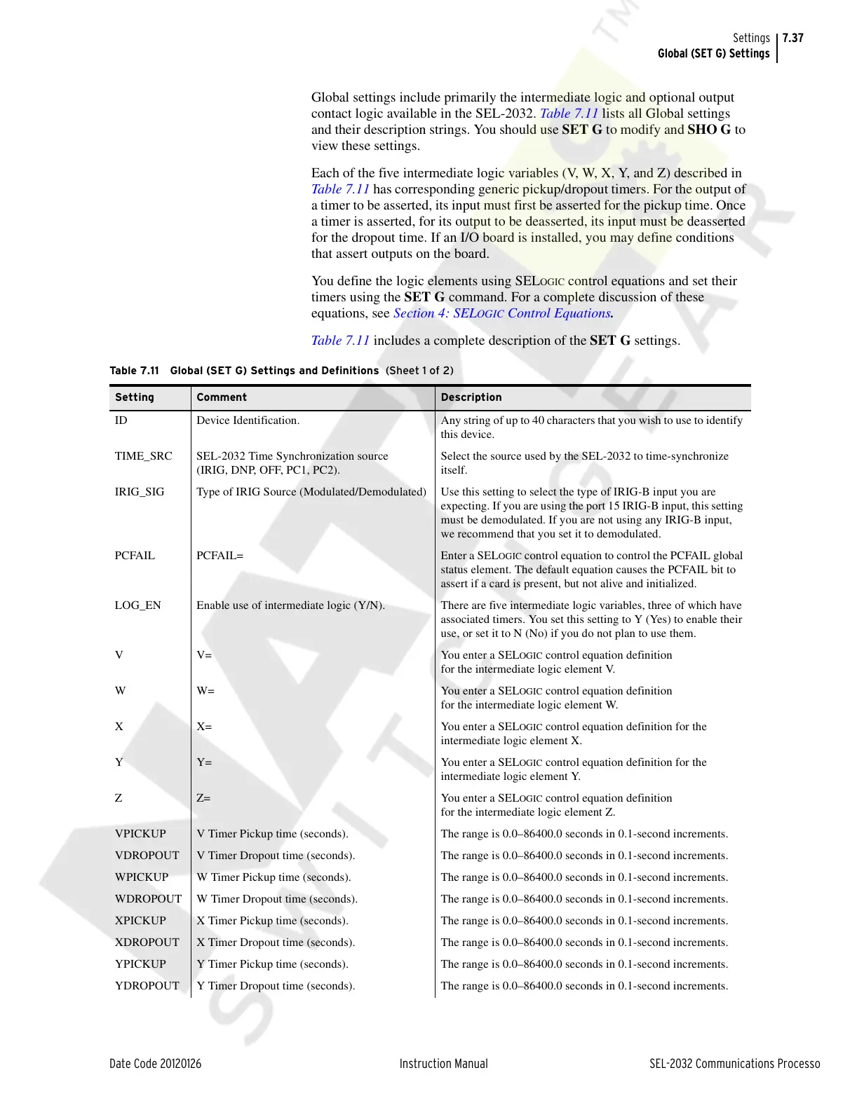
Table 7.11 Global (SET G) Settings and Definitions (Sheet 1 of 2)
Setting Comment Description
ID Device Identification. Any string of up to 40 characters that you wish to use to identify
this device.
TIME_SRC SEL-2032 Time Synchronization source
(IRIG, DNP, OFF, PC1, PC2).
Select the source used by the SEL-2032 to time-synchronize
itself.
IRIG_SIG Type of IRIG Source (Modulated/Demodulated) Use this setting to select the type of IRIG-B input you are
expecting. If you are using the port 15 IRIG-B input, this setting
must be demodulated. If you are not using any IRIG-B input,
we recommend that you set it to demodulated.
PCFAIL PCFAIL= Enter a SEL
OGIC control equation to control the PCFAIL global
status element. The default equation causes the PCFAIL bit to
assert if a card is present, but not alive and initialized.
LOG_EN Enable use of intermediate logic (Y/N). There are five intermediate logic variables, three of which have
associated timers. You set this setting to Y (Yes) to enable their
use, or set it to N (No) if you do not plan to use them.
V V= You enter a SEL
OGIC control equation definition
for the intermediate logic element V.
WW= You enter a SEL
OGIC control equation definition
for the intermediate logic element W.
XX= You enter a SEL
OGIC control equation definition for the
intermediate logic element X.
YY= You enter a SEL
OGIC control equation definition for the
intermediate logic element Y.
ZZ= You enter a SEL
OGIC control equation definition
for the intermediate logic element Z.
VPICKUP V Timer Pickup time (seconds). The range is 0.0–86400.0 seconds in 0.1-second increments.
VDROPOUT V Timer Dropout time (seconds). The range is 0.0–86400.0 seconds in 0.1-second increments.
WPICKUP W Timer Pickup time (seconds). The range is 0.0–86400.0 seconds in 0.1-second increments.
WDROPOUT W Timer Dropout time (seconds). The range is 0.0–86400.0 seconds in 0.1-second increments.
XPICKUP X Timer Pickup time (seconds). The range is 0.0–86400.0 seconds in 0.1-second increments.
XDROPOUT X Timer Dropout time (seconds). The range is 0.0–86400.0 seconds in 0.1-second increments.
YPICKUP Y Timer Pickup time (seconds). The range is 0.0–86400.0 seconds in 0.1-second increments.
YDROPOUT Y Timer Dropout time (seconds). The range is 0.0–86400.0 seconds in 0.1-second increments.
Courtesy of NationalSwitchgear.com