10.4
SEL-2032 Communications Processor Instruction Manual Date Code 20120126
Testing and Troubleshooting
Initial Checkout
Initial Checkout
Perform the following steps:
Step 1. Visually inspect the SEL-2032 for loose or damaged parts.
Step 2. Connect and apply power to the SEL-2032; see the PWR SUP
field on the rear-panel nameplate for power requirements.
If you do not have the proper voltage source available, use a
power supply, like the SEL-LPS, to power the unit.
Step 3. Press and hold the LED TEST button and confirm that all LEDs
illuminate.
Step 4. Connect a terminal (or computer equipped with terminal
emulation software) to the front-panel connector Port F of the
SEL-2032 using an SEL C234A cable or equivalent.
Step 5. Set the computer terminal or emulation software to operate at
the following settings:
➢ 2400 baud
➢ 8 data bits
➢ 1 stop bit
➢ no parity
Step 6. Press <Enter> and verify that an asterisk ( * ) prompt is
returned.
Step 7. Type ACCESS <Enter> to change to Access Level 1.
If you have not yet changed the password, enter the factory-set
password. You will see a screen similar to Figure 10.1, with the
password shown instead of ******.
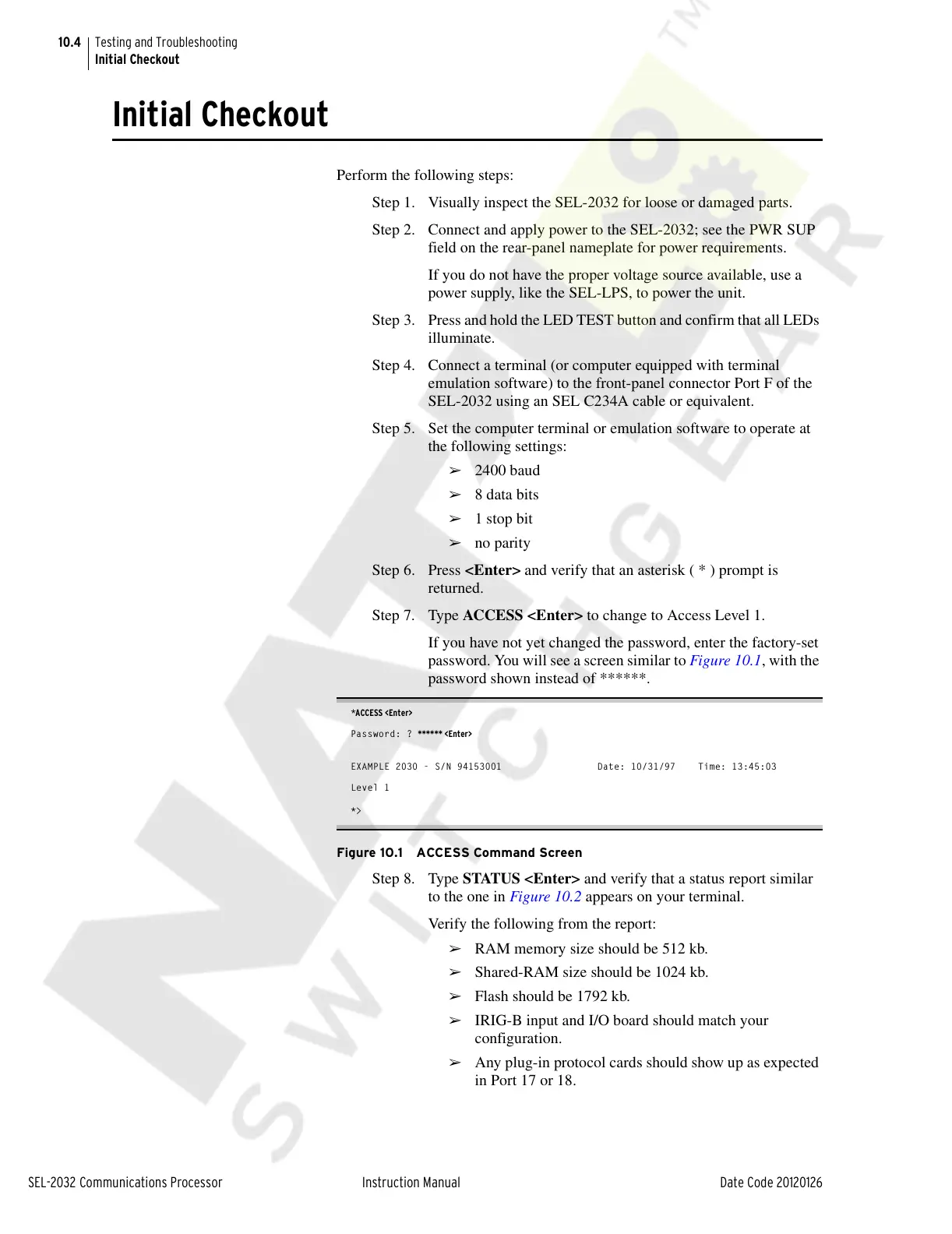
*ACCESS <Enter>
Password: ? ****** <Enter>
EXAMPLE 2030 - S/N 94153001 Date: 10/31/97 Time: 13:45:03
Level 1
*>
Figure 10.1 ACCESS Command Screen
Step 8. Type STATUS <Enter> and verify that a status report similar
to the one in Figure 10.2 appears on your terminal.
Verify the following from the report:
➢ RAM memory size should be 512 kb.
➢ Shared-RAM size should be 1024 kb.
➢ Flash should be 1792 kb.
➢ IRIG-B input and I/O board should match your
configuration.
➢ Any plug-in protocol cards should show up as expected
in Port 17 or 18.
Courtesy of NationalSwitchgear.com