2.15
Date Code 20120126 Instruction Manual SEL-2032 Communications Processor
Installation
Getting Started
Getting Started
Power up the SEL-2032 and follow the steps in Initial Checkout. Connect the
SEL-2032 to your station IEDs and configure it to collect data; see Collect
Data With the SEL-2032 on page 2.16.
Initial Checkout
Perform the following steps:
Step 1. Visually inspect the SEL-2032 for loose or damaged parts.
Step 2. Connect and apply power to the SEL-2032; see the POWER
SUPPLY field on the rear-panel nameplate for power
requirements.
If you do not have the proper voltage source available, use a
power supply, like the SEL-LPS, to power the unit.
If you wish, connect the SEL-2032 to a 120 Vac, US style 3-
prong outlet, use SEL cable C5305.
Step 3. Press and hold the LED TEST button and confirm that all LEDs
illuminate.
Step 4. Connect a computer equipped with terminal emulation
software to the front-panel connector Port F of the SEL-2032
using an SEL C234A cable or equivalent.
Connect the end of the cable labeled SEL (DTE) to the
SEL-2032 and the end labeled Computer/Terminal to your
computer 9-pin serial port.
Step 5. Set the computer terminal emulation software to operate at the
following settings:
➢ 2400 bits per second (sometimes called baud)
➢ 8 data bits
➢ 1 stop bit
➢ no parity
Step 6. Press <Enter> and verify that the SEL-2032 returns an asterisk
(*) prompt.
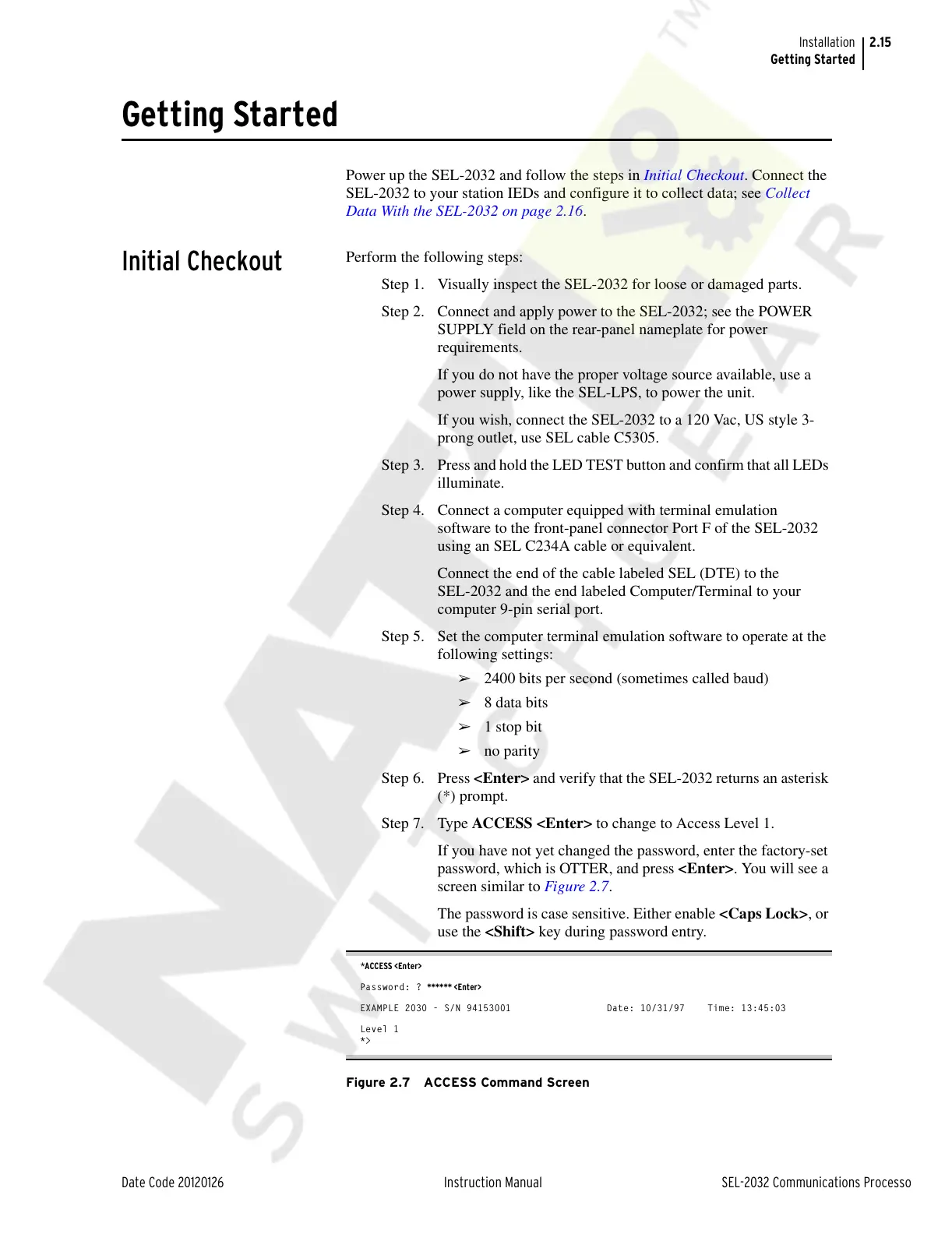
Step 7. Type ACCESS <Enter> to change to Access Level 1.
If you have not yet changed the password, enter the factory-set
password, which is OTTER, and press <Enter>. You will see a
screen similar to Figure 2.7.
The password is case sensitive. Either enable <Caps Lock>, or
use the <Shift> key during password entry.
*ACCESS <Enter>
Password: ? ****** <Enter>
EXAMPLE 2030 - S/N 94153001 Date: 10/31/97 Time: 13:45:03
Level 1
*>
Figure 2.7 ACCESS Command Screen
Courtesy of NationalSwitchgear.com