6.2
SEL-2032 Communications Processor Instruction Manual Date Code 20120126
Database
Database Structure
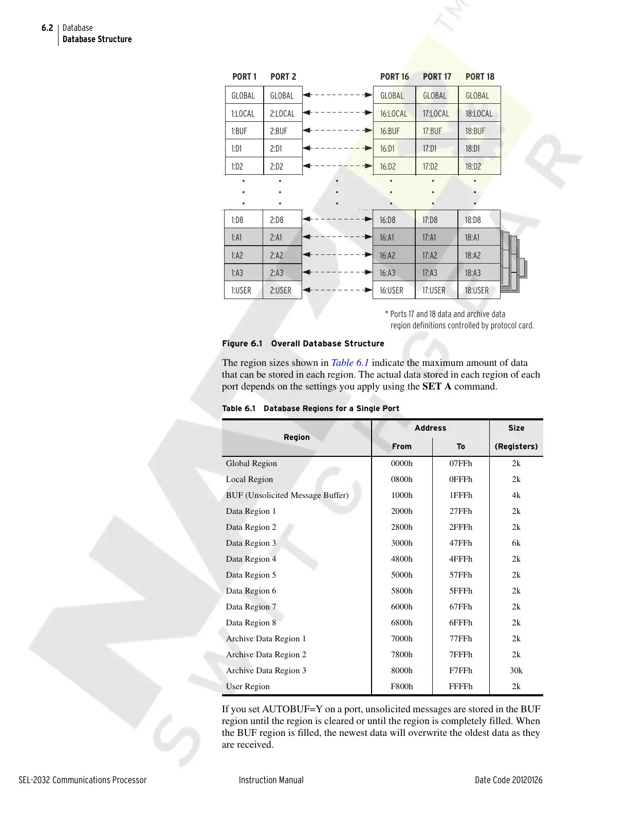
Figure 6.1 Overall Database Structure
The region sizes shown in Table 6.1 indicate the maximum amount of data
that can be stored in each region. The actual data stored in each region of each
port depends on the settings you apply using the SET A command.
If you set AUTOBUF=Y on a port, unsolicited messages are stored in the BUF
region until the region is cleared or until the region is completely filled. When
the BUF region is filled, the newest data will overwrite the oldest data as they
are received.
Table 6.1 Database Regions for a Single Port
Region
Address Size
From To (Registers)
Global Region 0000h 07FFh 2k
Local Region 0800h 0FFFh 2k
BUF (Unsolicited Message Buffer) 1000h 1FFFh 4k
Data Region 1 2000h 27FFh 2k
Data Region 2 2800h 2FFFh 2k
Data Region 3 3000h 47FFh 6k
Data Region 4 4800h 4FFFh 2k
Data Region 5 5000h 57FFh 2k
Data Region 6 5800h 5FFFh 2k
Data Region 7 6000h 67FFh 2k
Data Region 8 6800h 6FFFh 2k
Archive Data Region 1 7000h 77FFh 2k
Archive Data Region 2 7800h 7FFFh 2k
Archive Data Region 3 8000h F7FFh 30k
User Region F800h FFFFh 2k
2:D8
2:A1
2:A2
2:A3
2:USER
1:D8
1:A1
1:A2
1:A3
1:USER
GLOBAL
1:LOCAL
1:BUF
1:D1
1:D2
PORT 1
GLOBAL
2:LOCAL
2:BUF
2:D1
2:D2
PORT 2
GLOBAL
16:LOCAL
16:BUF
16:D1
16:D2
16:D8
16:A1
16:A2
16:A3
16:USER
PORT 16
GLOBAL
17:LOCAL
17:BUF
17:D1
17:D2
17:D8
17:A1
17:A2
17:A3
17:USER
PORT 17
GLOBAL
18:LOCAL
18:BUF
18:D1
18:D2
18:D8
18:A1
18:A2
18:A3
18:USER
PORT 18
* Ports 17 and 18 data and archive data
region definitions controlled by protocol card.
•
•
•
•
•
•
•
•
•
•
•
•
•
•
•
•
•
•
Courtesy of NationalSwitchgear.com