8.26
SEL-2032 Communications Processor Instruction Manual Date Code 20120126
Serial Port Communications and Commands
Command Set
A quartz crystal oscillator provides the time base for the internal clock. You
can also set the time clock automatically through the SEL-2032 time-code
input using a source of modulated or demodulated IRIG-B time code. The
SEL-2032 contains a battery-backed real-time clock, so the time and date will
be maintained through a loss of power.
TOGGLE m
The TOGGLE command (Access Level 2) toggles the specified element
(parameter m) for test purposes. You may specify global elements simply by
giving their name. Local elements must have the port number preceding the
element label (e.g., 4:D2). Toggle the Control Input and Output bits by
specifying the port and element label (e.g., 17:CCIN12). If that element can
trigger an operation, then that operation will occur. Use this command to test
your data collection and data access functions without having to force some
external condition.
When you use the TOGGLE command with the CCOUTn bits, internal logic
in the SEL-2032 executes normally. However, to reduce the likelihood of
misoperation due to testing in a network environment, the CCOUTn toggle
changes are not sent to the plug-in cards.
Normally, the toggled element will automatically toggle back as a result of
subsequent SEL
OGIC control equation calculations. However, if the specified
bit has an unused SEL
OGIC control equation, it will remain in the new state
until you use the TOGGLE command to return it to the original state. The
TOGGLE command is intended for test purposes only; you should use the
CONTROL command for operational control.
VIEW
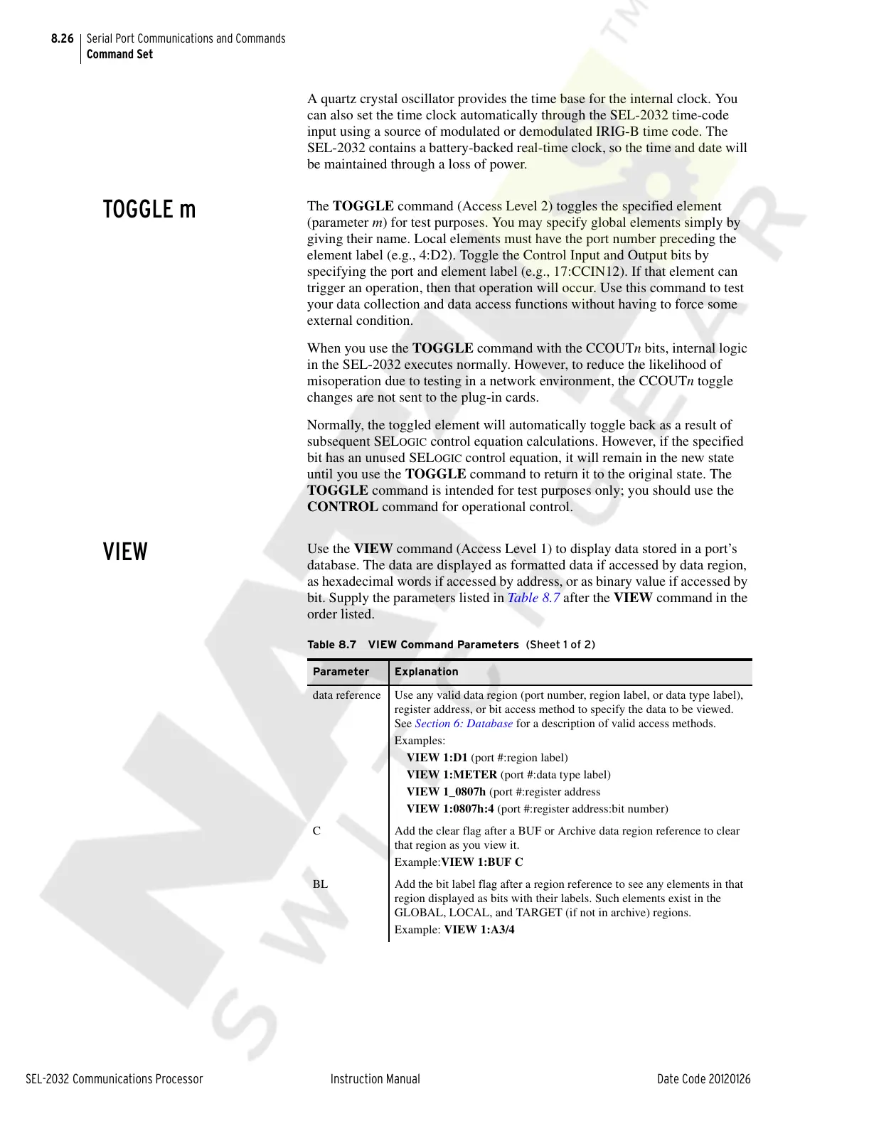
Use the VIEW command (Access Level 1) to display data stored in a port’s
database. The data are displayed as formatted data if accessed by data region,
as hexadecimal words if accessed by address, or as binary value if accessed by
bit. Supply the parameters listed in Table 8.7 after the VIEW command in the
order listed.
Table 8.7 VIEW Command Parameters (Sheet 1 of 2)
Parameter Explanation
data reference Use any valid data region (port number, region label, or data type label),
register address, or bit access method to specify the data to be viewed.
See Section 6: Database for a description of valid access methods.
Examples:
VIEW 1:D1 (port #:region label)
VIEW 1:METER (port #:data type label)
VIEW 1_0807h (port #:register address
VIEW 1:0807h:4 (port #:register address:bit number)
C Add the clear flag after a BUF or Archive data region reference to clear
that region as you view it.
Example:VIEW 1:BUF C
BL Add the bit label flag after a region reference to see any elements in that
region displayed as bits with their labels. Such elements exist in the
GLOBAL, LOCAL, and TARGET (if not in archive) regions.
Example: VIEW 1:A3/4
Courtesy of NationalSwitchgear.com