9.54
SEL-2032 Communications Processor Instruction Manual Date Code 20120126
Protocols
Distributed Network Protocol 3.0 (DNP3) LAN/WAN
Object Definitions
Data in the SEL-2032 can mapped to DNP3 automatically by the SEL-2701 or
with custom map files. Both methods allow a certain degree of customization,
but the more customized the maps are, the more configuration is required. The
DNP3 settings DNPMAP and DNPPAIR control the degree of customization
and configuration needed with either method.
Automatic Data Mapping
NOTE: Each time the SEL-2032
executes the SET M command to
populate its DNP port User data
region, it uses the time of execution
as the timestamp for all of the data
moved. Therefore, individual event
timestamps are ignored when
DNPMAP = AUTO. In order to preserve
SER timestamps for all input points
from an attached IED all the way
through to the DNP Master, you must
set DNPMAP = CUSTOM (see Custom
Data Mapping on page 9.56).
When DNPMAP = AUTO the SEL-2701 maps (to DNP3) input points—
binary, analog, and/or counter—that have already been moved to the Host’s
associated User data region. Similarly, the SEL-2701 maps up to 255 Analog
Outputs in the Host’s associated D1 data region, but it automatically creates
and populates this region. Binary Outputs are mapped to DNP3 based on the
DNPPAIR setting, discussed below.
Input Objects
Binary input, counter, and analog input objects are fully configurable by the
user. To make data visible to DNP3 when DNPMAP = AUTO, it must be
moved to the User data region on the SEL-2701 port (Port 17 or 18) using the
SET M process to establish what data are mapped and how they are to be
treated. See Section 7: Settings for more information on using SET M. To
determine the DNP3 data map once these settings are in place, establish a
virtual terminal session to the SEL-2701 with the PORT command and use
the DNPMAP command. See the SEL-2701 Instruction Manual for more
information on this command.
Output Objects: DNPPAIR = N
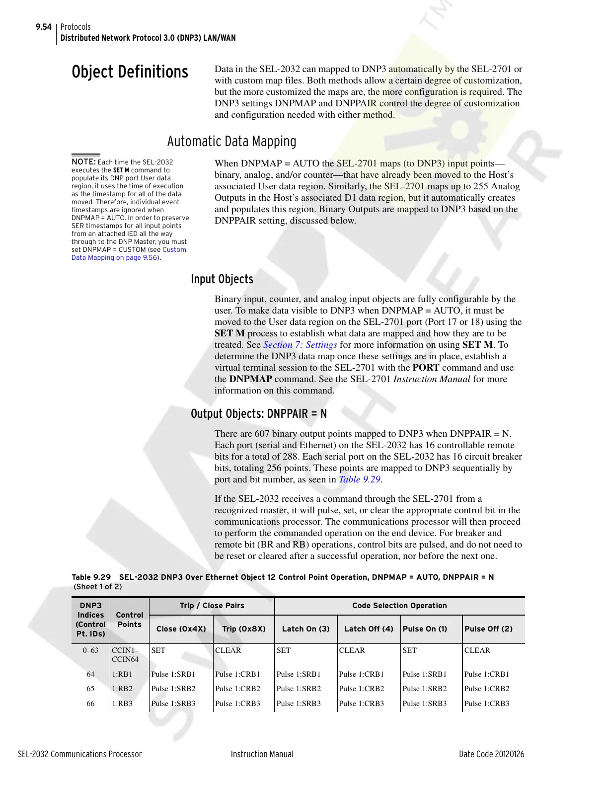
There are 607 binary output points mapped to DNP3 when DNPPAIR = N.
Each port (serial and Ethernet) on the SEL-2032 has 16 controllable remote
bits for a total of 288. Each serial port on the SEL-2032 has 16 circuit breaker
bits, totaling 256 points. These points are mapped to DNP3 sequentially by
port and bit number, as seen in Table 9.2 9 .
If the SEL-2032 receives a command through the SEL-2701 from a
recognized master, it will pulse, set, or clear the appropriate control bit in the
communications processor. The communications processor will then proceed
to perform the commanded operation on the end device. For breaker and
remote bit (BR and RB) operations, control bits are pulsed, and do not need to
be reset or cleared after a successful operation, nor before the next one.
Table 9.29 SEL-2032 DNP3 Over Ethernet Object 12 Control Point Operation, DNPMAP = AUTO, DNPPAIR = N
(Sheet 1 of 2)
DNP3
Indices
(Control
Pt. IDs)
Control
Points
Trip / Close Pairs Code Selection Operation
Close (0x4X) Trip (0x8X) Latch On (3) Latch Off (4) Pulse On (1) Pulse Off (2)
0–63 CCIN1–
CCIN64
SET CLEAR SET CLEAR SET CLEAR
64 1:RB1 Pulse 1:SRB1 Pulse 1:CRB1 Pulse 1:SRB1 Pulse 1:CRB1 Pulse 1:SRB1 Pulse 1:CRB1
65 1:RB2 Pulse 1:SRB2 Pulse 1:CRB2 Pulse 1:SRB2 Pulse 1:CRB2 Pulse 1:SRB2 Pulse 1:CRB2
66 1:RB3 Pulse 1:SRB3 Pulse 1:CRB3 Pulse 1:SRB3 Pulse 1:CRB3 Pulse 1:SRB3 Pulse 1:CRB3
Courtesy of NationalSwitchgear.com