17
Date Code 20120126 Instruction Manual SEL-2032 Communications Processor
Settings Sheets
SEL-2711, SET P
Date: ________________________________
Approved by: _________________________
SEL-2032 S/N: _______________________
SEL-2711, SET P
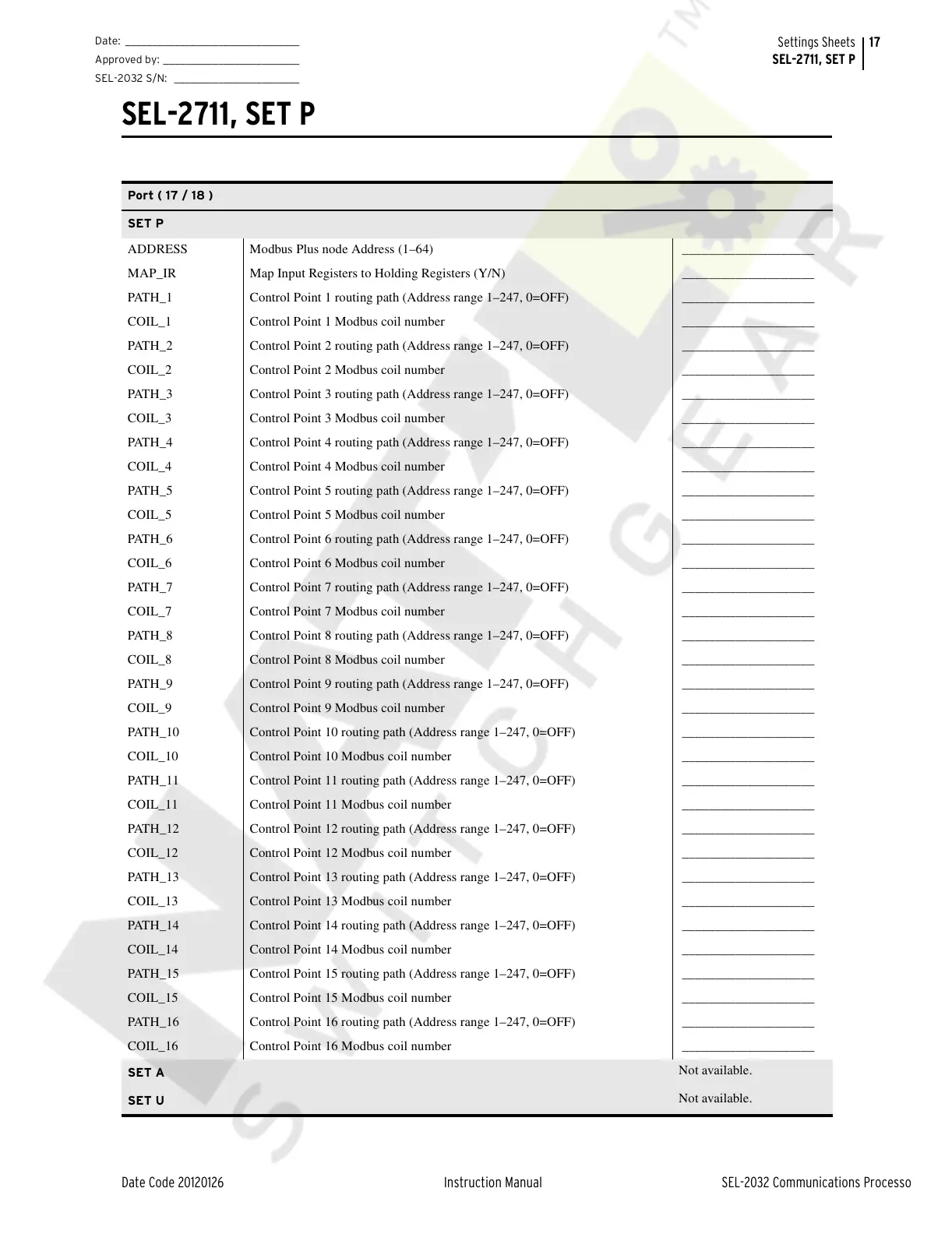
Port ( 17 / 18 )
SET P
ADDRESS Modbus Plus node Address (1–64) ____________________
MAP_IR Map Input Registers to Holding Registers (Y/N) ____________________
PATH_1 Control Point 1 routing path (Address range 1–247, 0=OFF) ____________________
COIL_1 Control Point 1 Modbus coil number ____________________
PATH_2 Control Point 2 routing path (Address range 1–247, 0=OFF) ____________________
COIL_2 Control Point 2 Modbus coil number ____________________
PATH_3 Control Point 3 routing path (Address range 1–247, 0=OFF) ____________________
COIL_3 Control Point 3 Modbus coil number ____________________
PATH_4 Control Point 4 routing path (Address range 1–247, 0=OFF) ____________________
COIL_4 Control Point 4 Modbus coil number ____________________
PATH_5 Control Point 5 routing path (Address range 1–247, 0=OFF) ____________________
COIL_5 Control Point 5 Modbus coil number ____________________
PATH_6 Control Point 6 routing path (Address range 1–247, 0=OFF) ____________________
COIL_6 Control Point 6 Modbus coil number ____________________
PATH_7 Control Point 7 routing path (Address range 1–247, 0=OFF) ____________________
COIL_7 Control Point 7 Modbus coil number ____________________
PATH_8 Control Point 8 routing path (Address range 1–247, 0=OFF) ____________________
COIL_8 Control Point 8 Modbus coil number ____________________
PATH_9 Control Point 9 routing path (Address range 1–247, 0=OFF) ____________________
COIL_9 Control Point 9 Modbus coil number ____________________
PATH_10 Control Point 10 routing path (Address range 1–247, 0=OFF) ____________________
COIL_10 Control Point 10 Modbus coil number ____________________
PATH_11 Control Point 11 routing path (Address range 1–247, 0=OFF) ____________________
COIL_11 Control Point 11 Modbus coil number ____________________
PATH_12 Control Point 12 routing path (Address range 1–247, 0=OFF) ____________________
COIL_12 Control Point 12 Modbus coil number ____________________
PATH_13 Control Point 13 routing path (Address range 1–247, 0=OFF) ____________________
COIL_13 Control Point 13 Modbus coil number ____________________
PATH_14 Control Point 14 routing path (Address range 1–247, 0=OFF) ____________________
COIL_14 Control Point 14 Modbus coil number ____________________
PATH_15 Control Point 15 routing path (Address range 1–247, 0=OFF) ____________________
COIL_15 Control Point 15 Modbus coil number ____________________
PATH_16 Control Point 16 routing path (Address range 1–247, 0=OFF) ____________________
COIL_16 Control Point 16 Modbus coil number ____________________
SET A
Not available.
SET U
Not available.
Courtesy of NationalSwitchgear.com