9.15
Date Code 20120126 Instruction Manual SEL-2032 Communications Processor
Protocols
Modbus RTU Protocol
In all cases, bit numbering starts with the LSB of each register. See Section 6:
Database for a description of these registers. To access relay target data, you
must set a region to collect the target data. Then, using the MAP n TARGET
BL command, you can determine how many bytes of target data exist and
what each bit is. The first target element is accessible at 1100h.
When referencing the data from most masters, you will need to set the coil
number one greater than the listed bit address (0X references).
Read Input Status (Function Code 02h)
Function code 02h is used in a manner identical to function code 01h, as
discussed above. Most masters use 1X references with this function code. To
find the 1X reference with 5-digit addressing, add 10001 to the bit address
specified above.
Read Holding Register (Function Code 03h)
The SEL-2032 uses function code 03h to read from the database directly.
Refer to Section 6: Database for a description of the database. Use the MAP
command to determine the details of the register maps based on your settings.
You can read a maximum of 125 registers at once with function code 03.
Most masters use 4X references with this function code. Under certain
circumstances, you may need to use 5- or 6-digit addressing to access these
registers. To find the 4X reference with 5-digit addressing, add 40001 to the
database addresses. For addresses above 9999 (270Fh), the SEL-2032 requires
the master to use 6-digit addressing to avoid corrupting the type identifier digit
4. To find the 4X reference with 5-digit addressing, add 40001 to the database
addresses. For example, the first register in the user region is at address F800h,
which is converted to 463489 for 6-digit addressing. To read the user region
with 5-digit addressing, you can access the registers as 3X using function code
04h, but you may suffer a performance hit (see Read Input Register (Function
Code 04h) on page 9.16).
If your Modbus master cannot access data in the user region, you can use the
20USER command to copy data to a more accessible address range (see
Example 6: Modbus Job Done on page 3.26).
The master request must have the following format:
1 byte. Slave Address
1 byte. Function code (03h)
2 bytes. Starting database address
2 bytes. Number of registers to read
2 bytes. CRC–16 for message
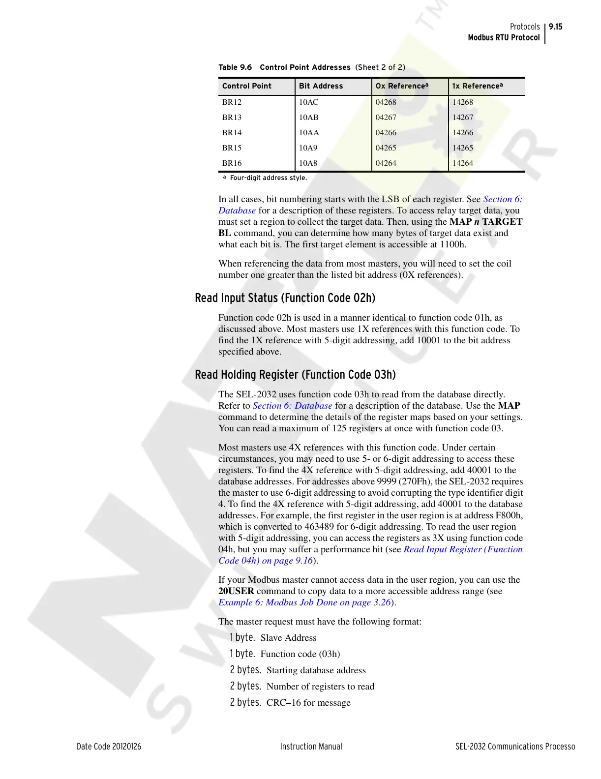
BR12 10AC 04268 14268
BR13 10AB 04267 14267
BR14 10AA 04266 14266
BR15 10A9 04265 14265
BR16 10A8 04264 14264
a
Four-digit address style.
Table 9.6 Control Point Addresses (Sheet 2 of 2)
Control Point Bit Address 0x Reference
a
1x Reference
a
Courtesy of NationalSwitchgear.com