Section 04 FUEL SYSTEM
Subsection 02 (FUEL TANK AND FUEL PUMP)
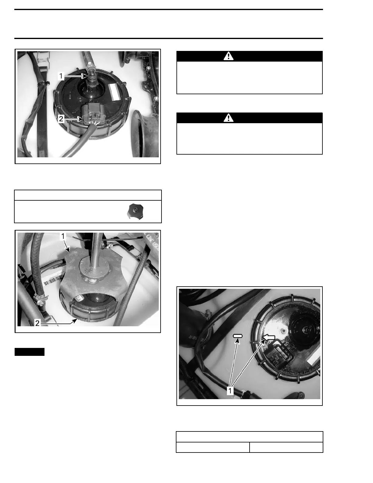
smr2012-027-010_b
1. Quick connect fitting (high pressure fuel hose)
2. Harness connector
5. Unscrew the fuel pump retaining nut.
REQUIRED TOOL
FUEL PUMP MODULE SOCKET
(P/N 529 036 125)
smr2009-031-022_a
1. Fuel p
ump module socket
2. Fuel pump retaining nut
NOTIC
E
While pulling out the fuel pump
module, pay attention to the corrugated tubes
and fuel sensor float arm. Float arm can get
caught up and bend which will reduce fuel sen-
sor accuracy. If fuel pump module is dropped
or damaged, it must be replaced.
6. Slow
ly pull fuel pump module up through
open
ing until corrugated tubes contact sides
of op
ening. Tilt the fuel pump module as you
slow
ly pull the pump upwards.
WARNING
The upper filter and fuel pump reservoir on
the fuel pump module contain fuel which will
drain out when fuel pump module is not in an
upright position.
7. Carefully pu
ll fuel pump module out.
WARNING
Always wipe off any fuel spillage from the
watercraft. When working with fuel or fuel
system and its components, always work in
a well ventilated area.
Installing the Fuel Pump
Reverse the removal procedure however, pay at-
tention to the following.
1. Carefully insert fuel pump module in fuel tank
so as not to bend float arm.
2. Install a NEW fuel pump module gasket each
time the module is reinstalled.
NOTE: Wipe off parts to prevent fuel pump from
turning while torquing fuel pump nut.
3. Align a rrow on top of fuel pump module with
index mark on top of fuel tank or fuel sensor
accuracy will be affected.
NOTE: Index mark and arrow locations are high-
lighted for clarity in following illustration.
smr2012-027-012_a
FUEL
PUMP MODULE INDEXING
1. Align marks
4. Tighten fuel pump nut.
TIGHTENING TORQUE
Fuel pump nut 60 N•m (44 lbf•ft)
96 219100893-021

 Loading...


