Section 04 FUEL SYSTEM
Subsection 02 (FUEL TANK AND FUEL PUMP)
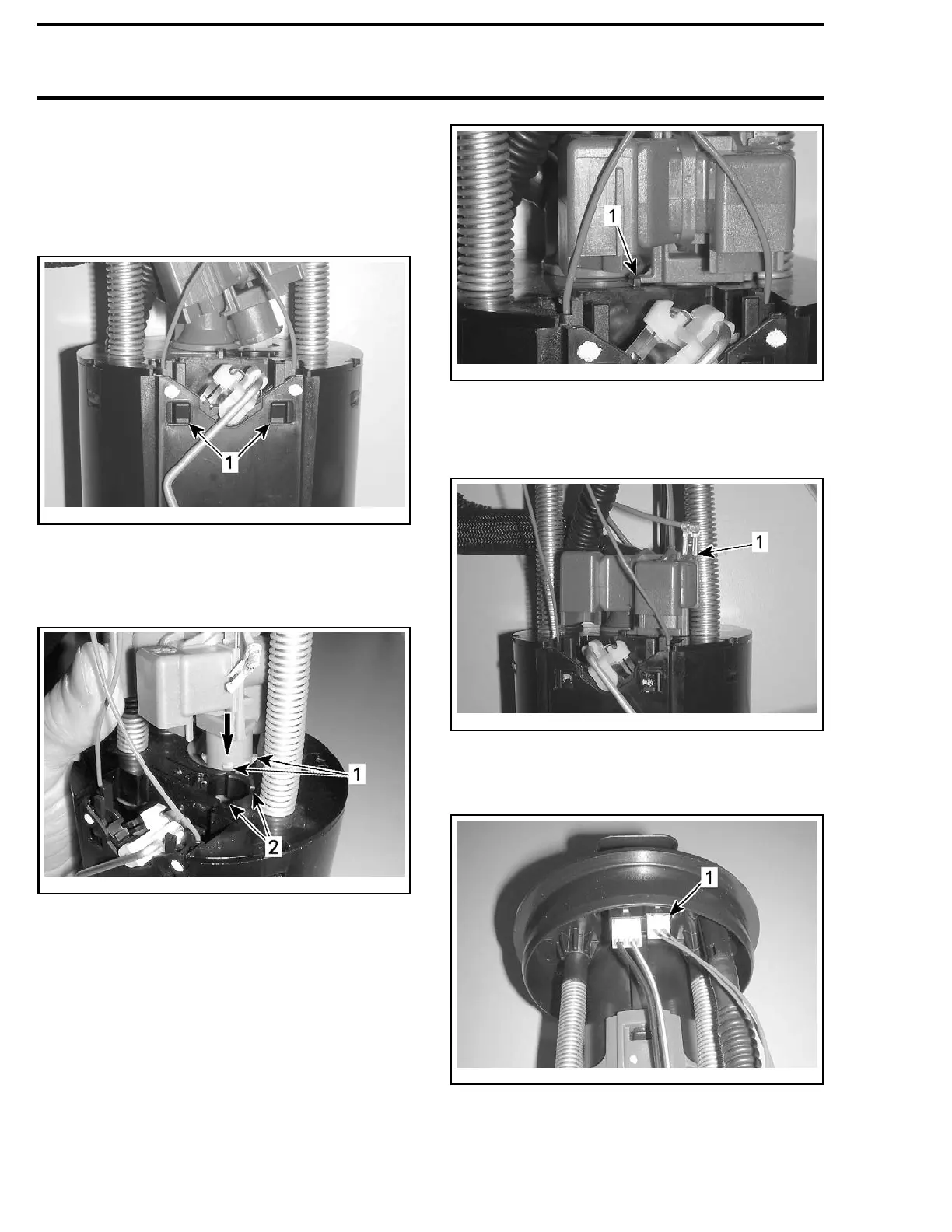
Installing the Fuel Level Sensor
Installation is the reverse of the removal proce-
dure however, pay attention to the following.
1. Ensure fuel level sensor locking pins are prop-
erly engaged into the fuel pump reservoir.
smr2008-022-026_b
1. Ensure en
gagement of sensor locking pins
2. Align the fuel pressure regulator tabs into the
pump reservoir cover and turn it counterclock-
wise until it locks properly.
smr2008-022-025_b
PRESSURE REGULATOR INSERTION INTO PUMP RESERVOIR
COVER
1. Pressure regulator alignment tabs
2. Fuel pump reservoir alignme nt tabs
smr2008-022-030_a
TAB UP WHEN PRESSURE REGULATOR PROPERLY LOCKED
1. Pressure regulator locking tab
3. Reconnect the ground wire onto the pressure
regulator.
smr2008-022-031_a
1. Pressu
re regulator ground wire installed
4. Ensure fuel level sensor connector is locked
into the module flange connector.
smr2008-022-021_a
1. Fuel level sensor connector
5. Test fuel level sensor resistance as described in
this subsection.
102 219100893-021

 Loading...


