Section 06 ST EE RING AND PROPULSION
Subsection 02 (iBR, REVERSE AND VTS)
219100893-029-008_a
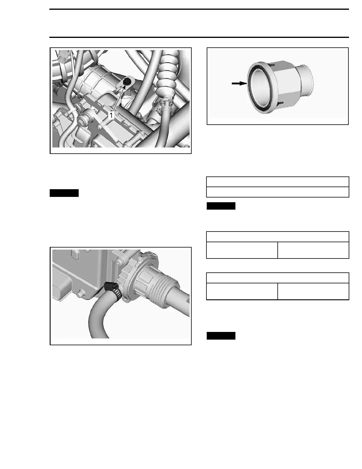
1. Actuator retaining screw
9. Remove iBR actuator and air chamber.
Installing the iBR Actuator
NOTICE
Failure to adhere to the sequence in
the following steps will cause the iBR air cham-
ber to rupture or burst and cause premature
failure of the iBR actuator.
1. Install the air chamber on the iBR actuator.
1.1 Tighten the clamp.
smr20
16-036-036
2. Connect iBR actuator connector.
3. Install iBR actuator shaft through hull opening.
4. Slide the O-ring into position on iBR nut.
smr2016-036-013_a
5. If the same actuator is reinstalled, clean
all residues of sealing compound near the
threaded area.
6. Apply Loctite 5900 on actuator, between actu-
ator housing and threads, as shown in the ex-
ploded view.
SERVICE PR
ODUCT
LOCTITE 5900 (P/N 293 800 066)
NOTICE
Ensure no sealing agents contact the
iBR shaft.
7. Torque iBR nut.
TIGHTENING TORQUE
iBR nut
17.5 N•m ± 2.5 N•m
(155 lbf•in ±22lbf•in)
8. Install actuator retaining screw.
TIGHTENING TORQUE
Actuat
or retaining screw
8N•m ± 1N•m
(71 lbf•in ±9lbf•in)Text
9. Insta
ll connecting arm.
10. Reinstall other removed parts. Refer to appro-
priate subsections for procedures.
NOTICE
Allo
w 24 hours for thread locker on
reta
ining screws to cure.
Perform
iBR FLASHING
procedure.
Perf
orm
iBR AUTO-CALIBRATION
procedure.
219100963-018 177

 Loading...


