190
Relay Operation Testing
1. Disconnect the negative ( - ) battery
cable from the battery.
2. Disconnect and remove the relay to be
tested from the tractor.
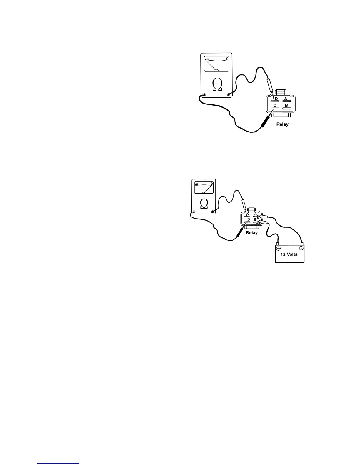
3. Using an ohmmeter, connect test probes
to terminals "C" and "D" on the relay
observe the ohmmeter reading.
4. There should be high resistance between
terminals "C" and "D", indicating no
continuity and that the relay is
functioning properly when non-energized.
If there is continuity, the relay is
defective and needs replaced.
5. To test the relay when energized, use
jumper wires to connect a 12-volt power
supply to terminals "A" and "B" (brass
terminals) on the relay.
6. Touch ohmmeter test probes to the "C"
and "D" terminals on the relay and
observe the ohmmeter. Little or no
resistance between the terminals
indicates that there is continuity and that
the relay is functioning properly. If there
is no continuity between the terminals,
the relay is defective and needs replaced.
7. Install the relay onto the tractor.
8. Connect the negative (- ) battery cable
to the battery.
527Y
528Y