197
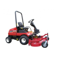
15) RELAY FOR HST BRAKE
SWITCH
Description
The relay for HST brake switch is located on
the steering column in the dash board, and it
is connected with blue color connector on
the HST circuit wire harness.
Relay is used to automatically open a circuit.
A relay contains two parts of a circuit. One
part, the control circuit, uses current to
energize a coil.
The other part, the function circuit, is a
switch. When energized, the coil of a relay
becomes an electromagnet opening or
closing a single circuit.
The HST brake switch relay utilizes
single-pole, single-throw switches (SPST).
The function circuits are normally close
when no current is being supplied to the coil.
If a circuit with an SPST relay is energized
with current, the switch becomes opened.
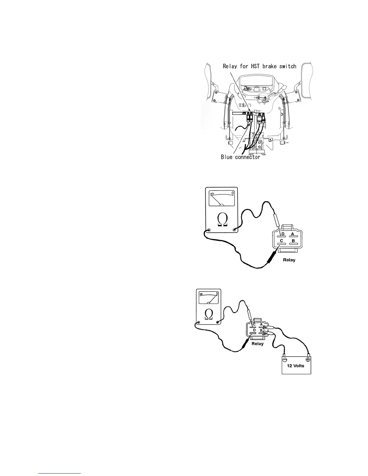
Relay Operation Testing
1. Disconnect the negative (-) battery cable
from the battery.
2. Disconnect and remove the relay to be
tested from the tractor.
3. Using an ohmmeter, connect test probes
to terminals "C" and "D" on the relay.
Observe the ohmmeter reading.
4. There should be high resistance between
terminals "C" and "D", indicating
continuity and that the relay is
functioning properly when
non-energized. If there is no continuity,
the relay is defective and needs
replaced.
5. To test the relay when energized, use
jumper wires to connect a 12-volt power
supply to terminals "A" and "B" (brass
terminals) on the relay.
6. Touch ohmmeter test probes to the "C"
and "D" terminals on the relay and
observe the ohmmeter. High resistance
between the terminals indicates that
there is no continuity and that the relay
is functioning properly. If there is
continuity between the terminals, the
relay is defective and needs replaced.
7. Install the relay onto the tractor.
8. Connect the negative (-) battery cable to
the battery.
547Y
548Y
549Y
 Loading...