211
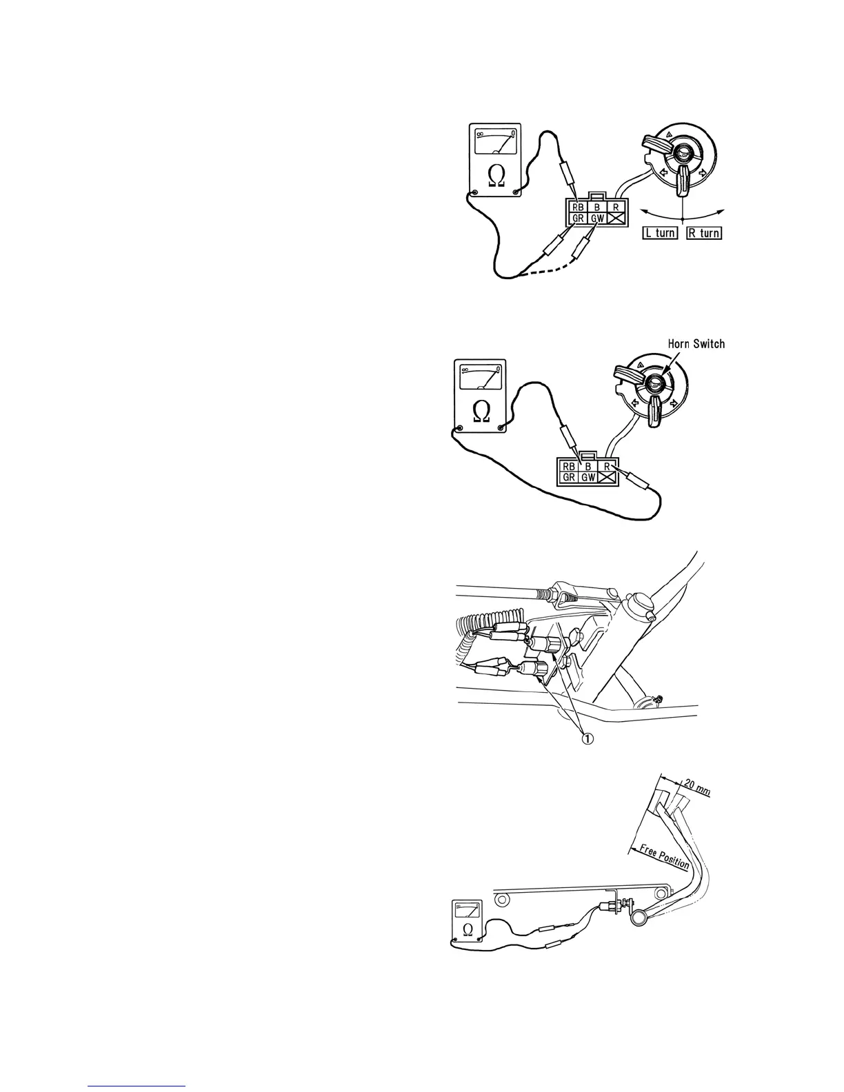
B. Flasher Light Switch Testing
Use an ohmmeter to test the flasher light
switch.
1. With the switch in the "OFF" position,
there will not be continuity between any
of the terminals.
2. With the switch in the “ R turn”position,
there will be continuity between
terminals RB and GW.
3. With the switch in the “ L turn”position,
there will be continuity between
terminals RB and GR.
If test results are not as outlined above,
replace the combination switch.
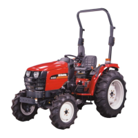
C. Horn Switch Testing
Use an ohmmeter to test the horn switch.
1. With the switch in the "OFF" position,
there will not be continuity between any
of the terminals.
2. With the switch at the “ push” position,
there will be continuity between
terminals B and R.
If test results are not as outlined above,
replace the combination switch.
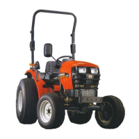
25) BRAKE LAMP SWITCH
Description and Location
The master brake switch, 1, is a single pole,
pullout-plunger type switch. The switches
are located under the right side of the
operator’s on the master brake linkage. The
switch is closed when the brake pedal is
depressed about 20mm.
When the brake pedal is not depressed, the
switch contacts are open.
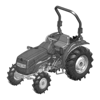
Adjustment
If the master brake switch is suspected of
being defective, check the adjustment of the
switch before replacing. The switch also
needs adjusted if removed from the tractor.
To adjust the switch use the following
procedure:
1. Using an ohmmeter connect test leads to
each terminals on the each switches and
observe the ohmmeter.
2. Adjust the brake switch is closed
position by bolt and lock nut when
depress the brake pedal to 20mm.
576Y
577Y
578Y
579Y