210
24) COMBINATION SWITCH
DESCRIPTION
Hazard Light Switch Description
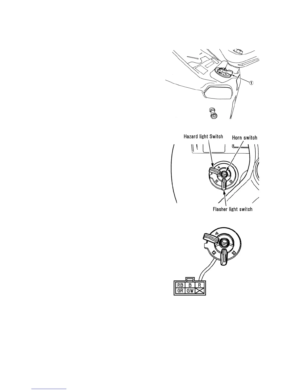
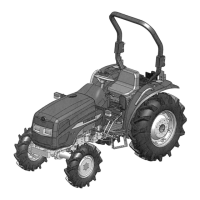
The combination switch is located on the
left-hand side of the dashboard. The
combination switch consists of hazard light
switch, flasher light switch and horn switch.
The hazard and flasher switch, 1, are dial
switch and horn switch is a push button
switch. The two positions of the hazard
light switch are ON and OFF. When the
hazard light switch is in the "ON" position,
the flasher/warning lights on the fenders will
operate.
NOTE: The hazard lights can be activated
with the key switch in the "OFF" position.
Flasher Light Switch Description
The three positions of the flasher light
switch are OFF, Right turn and Left turn.
When the flasher light switch is in the
“ Right” or“ Left” turn position, the flasher
lights on the fender and instrument panel
will operate.
Horn Switch Description
The horn switch is pushed ON type switch.
When the horn switch is pushed, horn circuit
is complete and alarm the horn.
Combination Switch Removal
Remove the instrument panel to gain access
to the combination switch. To remove the
switch, unplug it from the harness, release
the retaining tabs, and lift the switch out of
the instrument panel from the top.
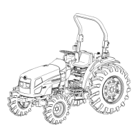
A. Hazard Light Switch Testing
Use an ohmmeter to test the hazard light
switch.
1. With the switch in the "OFF" position,
there will not be continuity between any
of the terminals.
2. With the switch in the "ON" position,
there will be continuity between
terminals GW, RB and GR.
If test results are not as outlined above,
replace the combination switch.
573Y
574Y
575Y