Input/output modules
5-36 Hardware - SIMADYN D
Edition 12.2004
IT42
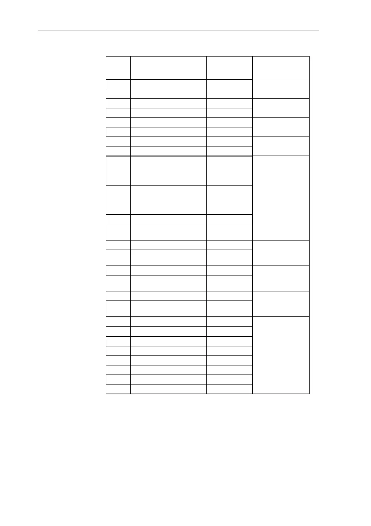
X7
Significance SU10 Connector
designation when
configuring
1 ADU analog input 1+ 1 X7A
14 ADU analog input 1- 2
2 ADU analog input 2+ 3 X7B
15 ADU analog input 2- 4
3 ADU analog input 3+ 5 X7C
16 ADU analog input 3- 6
4 ADU analog input 4+ 7 X7D
17 ADU analog input 4- 8
5 Reference ground for
differential ADU analog
inputs
(due to push-pull)
9
18 Reference ground for
differential ADU analog
inputs
(due to push-pull)
10
6
Analog output 1+
11 X7E
19 Ground, inductively de-
coupled
12
7 Analog output 2+ 13 X7F
20 Ground, inductively de-
coupled
14
8 Analog output 3+ 15 X7G
21 Ground, inductively de-
coupled
16
9 Analog output 4+ 17 X7H
22 Ground, inductively de-
coupled
18
10 Ground 19
23 Ground 20
11 Not connected 21
12 Not connected 22
13 Not connected 23
24 Not connected 24
25 Not connected 25
- Not connected 26
Table 5-29 Pin assignment IT42, connector X7 and terminal assignment SU10
Analog
inputs/outputs
at X7 with SU10

 Loading...


