Technology subrack
7-8 Hardware - SIMADYN D
Edition 03.2001
9.6 kbaud
19.2 kbaud
38.4 kbaud
93.75 kbaud
187.5 kbaud
7.2.5.1 Bus termination
Bus terminating resistors for serial interfaces 1- and 2 can be switched-in via
switch S1/1-S1/8 if the T400 is located at the beginning or end of the bus.
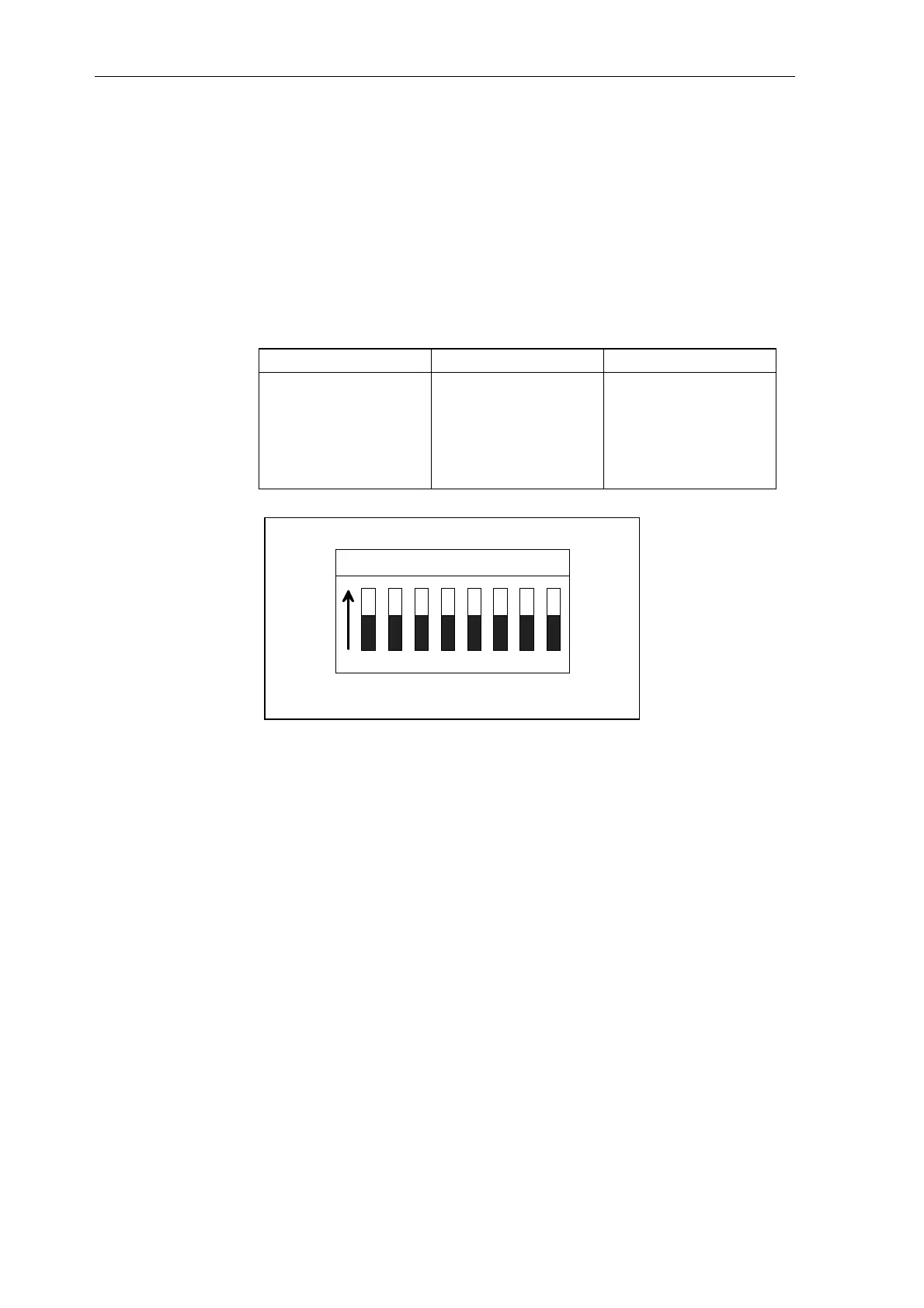
Terminals Switch S1
Serial interface 1 70/71 1,2
Serial interface 2
(2-conductor, 4-
conductor)
74/75 3,4
Serial interface 2
(4-conductor)
72/73 5,6
ON
23456781
Fig. 7-3 Switch S1
The terminating resistors are switched-in in the ON setting.
The switch settings can only be changed after the module has been
withdrawn. These switches are not accessible if the module is inserted.
Switch S7 has no function.
7.2.5.2 Communications switch
Switch S1/8 toggles between the service- and USS protocol at serial
interface 1. More detailed information can be taken from the description of
the USS protocol.

 Loading...


