Communications support modules
Hardware - SIMADYN D 6-33
Edition 12.2004
6
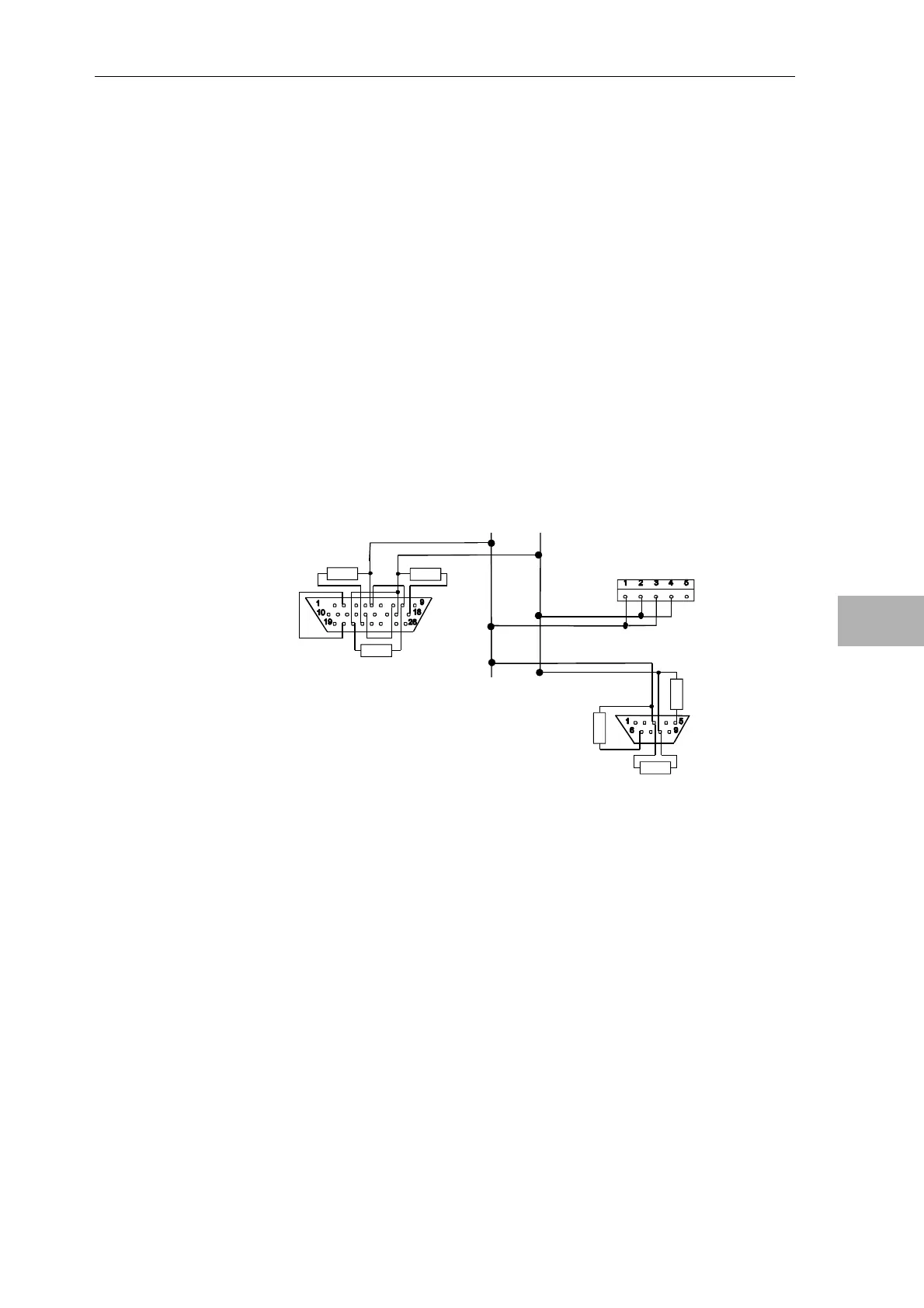
6.8.2 USS connection for OP2, VD1
Connecting cables for the OP2 operator control device or the VD1 numerical
display can be assembled using the SM8 parts set (for SS4) or an
appropriate parts set for OP2/VD1 (OP2: Parts set SM5) according to the
following diagrams.
A 4-core screened round cable is required (e. g. LICYC 4*0,5, Metrofunk).
In order to increase the data integrity, the bus cable at both ends (at the first
and last nodes) must be terminated using a resistor network:
• an 150Ω resistor between the RS485+, RS485- data signal lines
• one 390Ω resistor each from the data signal cables RS485+ to +5 V and
from RS485- to ground to define a quiescent signal level when a node is
not transmitting („basis network“)
For the VD1 numerical display, the bus termination (including basis
network) is already integrated in the unit. These can be activated using the
two DIL switches S1/S2.
RS485+
390R
390R
150R
SS4
RS485-
S1 - ON
S2 - ON
VD1
OP2
390R
390R
150R
Fig. 6-10 SS4 at OP2 and VD1; with bus terminating circuitry
Bus termination
USS bus with
connection

 Loading...


